
The most significant development in the next-generation Roadster unveiled on October 15, 2026 is not a further increase in motor power, but the integration of tire loading, electrical power delivery, underbody suction and short-duration gas thrust into a single vehicle-motion-control problem. Working through four levels of evidence — physical hardware and public statements, patent disclosure, engineering analysis, and items awaiting verification — this report starts from the live demonstration and checks the physical basis and engineering costs of fan suction, cold-gas propulsion and the active rear wing system by system, closing with a validation checklist for the path from prototype to product. The subject is the new platform made public in 2026; specifications from the 2017 concept are not carried over, and the report draws on public sources verifiable as of October 18, 2026.
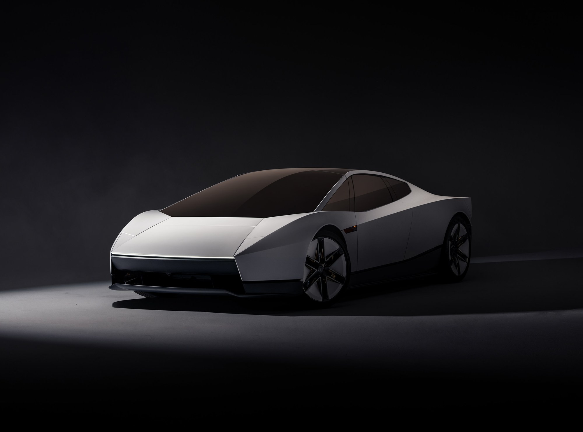
Overview of the live demonstration
The live demonstration of the next-generation Roadster can be approached through four readily visible actions: traveling along an elevated curved surface, clearing vehicles used as obstacles, rolling in the air, and descending after returning upright. These extend a sports car’s performance beyond acceleration and cornering on a flat plane to encompass its relationship with the road surface, changes in orientation after leaving the ground, and its return to the ground. Establishing what these actions show gives the later discussion of fans, skirts, gas storage and nozzles concrete phenomena to explain.
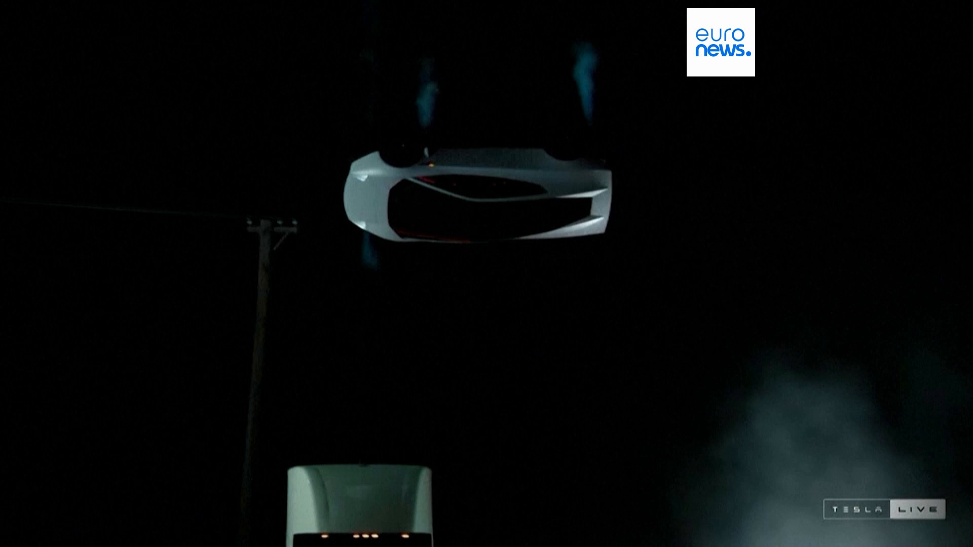
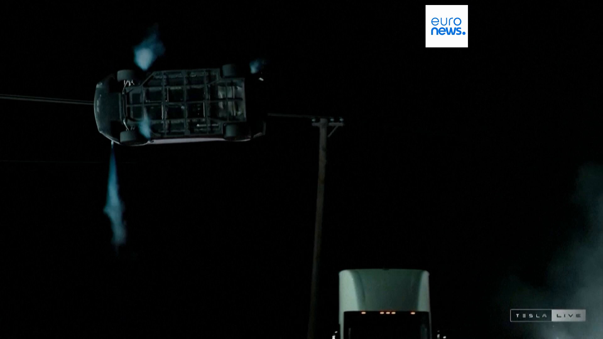
The surface-adhesion demonstration is notable for the body’s steep inclination along the curved surface, with the wheel side still facing and remaining close to that surface. The obstacle-clearing demonstration shows enough space between the car and the ground for it to pass over other vehicles. During the aerial roll, the roof, side and underside face the audience in turn, revealing changes in body attitude. The landing reconnects these actions with the most familiar state of a car: wheels downward, approaching the ground, with the tires and suspension then taking the supporting loads.
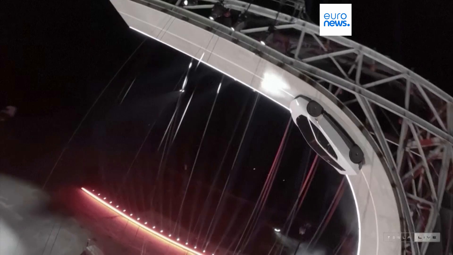
Taken together, these four actions make the central theme of the product demonstration clear: maintaining contact while on a surface, changing motion and attitude after leaving it, and finally returning smoothly to the ground. They introduce the questions of grip, thrust, attitude control and landing loads discussed later. This section arranges the live footage in that explanatory order. The news video includes edits and camera changes, so the images below cannot be assembled into a single uninterrupted sequence.
Clearing obstacles
The obstacle demonstration turns ‘leaving the ground’ into an easily understood spatial relationship: a white truck and other vehicles are identifiable in the frame, and the demonstration car passes above them. The scene shows the car clearing physical obstacles, allowing readers to observe directly the relative positions of the vehicle, obstacles and ground.
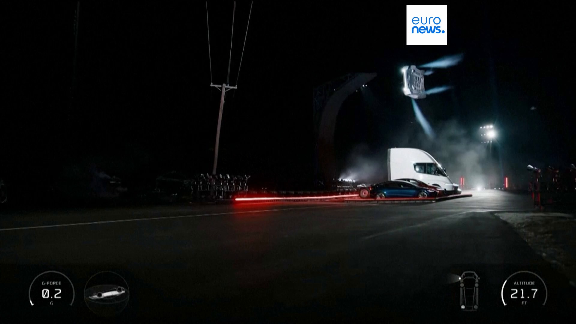
This differs from the surface-adhesion demonstration in the previous section: once the wheels leave the contact surface, the tires can no longer transmit driving or steering forces as they do on a road. Explaining the airborne motion requires considering the velocity already acquired at takeoff, gravity, and any additional thrust that may have been applied during the demonstration. The later sections therefore discuss tire traction and gas discharge separately, rather than attributing every action to motor power.
This frame is useful for answering ‘What did the car clear in the demonstration?’ It cannot, by itself, establish jump height, horizontal distance or maximum load-carrying capability. Actual product capability still requires known dimensions, continuous recordings and clearly defined test conditions.
Airborne attitude adjustment and roll
Leaving the ground is not the end of the maneuver. Another set of live shots shows the body rolling in the air and then returning toward a wheels-down attitude. The roll changes the orientation of the entire vehicle; it is a different maneuver from cornering on the ground. It also provides a visual clue to how the body is brought upright for the subsequent descent.
Upright descent and landing phase
After the roll, the vehicle in the live footage returns to a wheels-down attitude and descends toward the ground. This concluding action is equally important: airborne changes in attitude must ultimately transition into tire contact, requiring coordination of body orientation, descent speed and suspension loads.
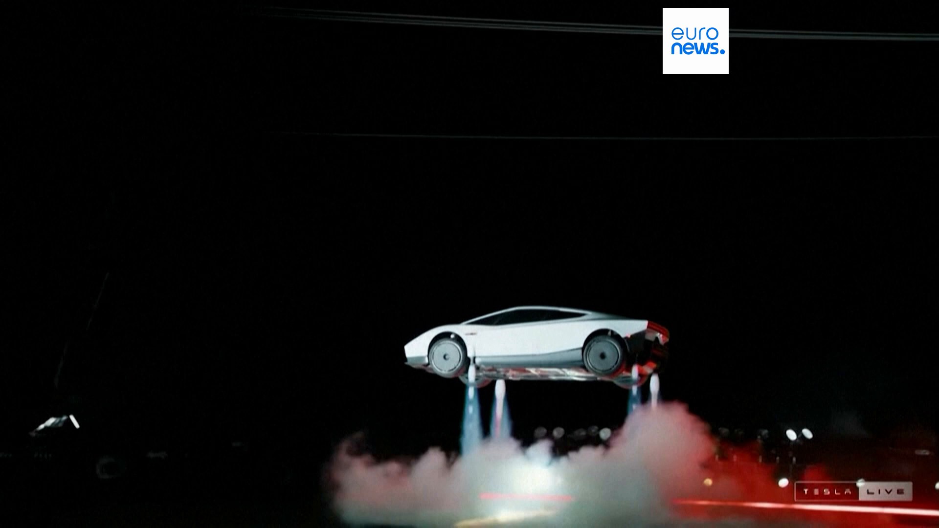
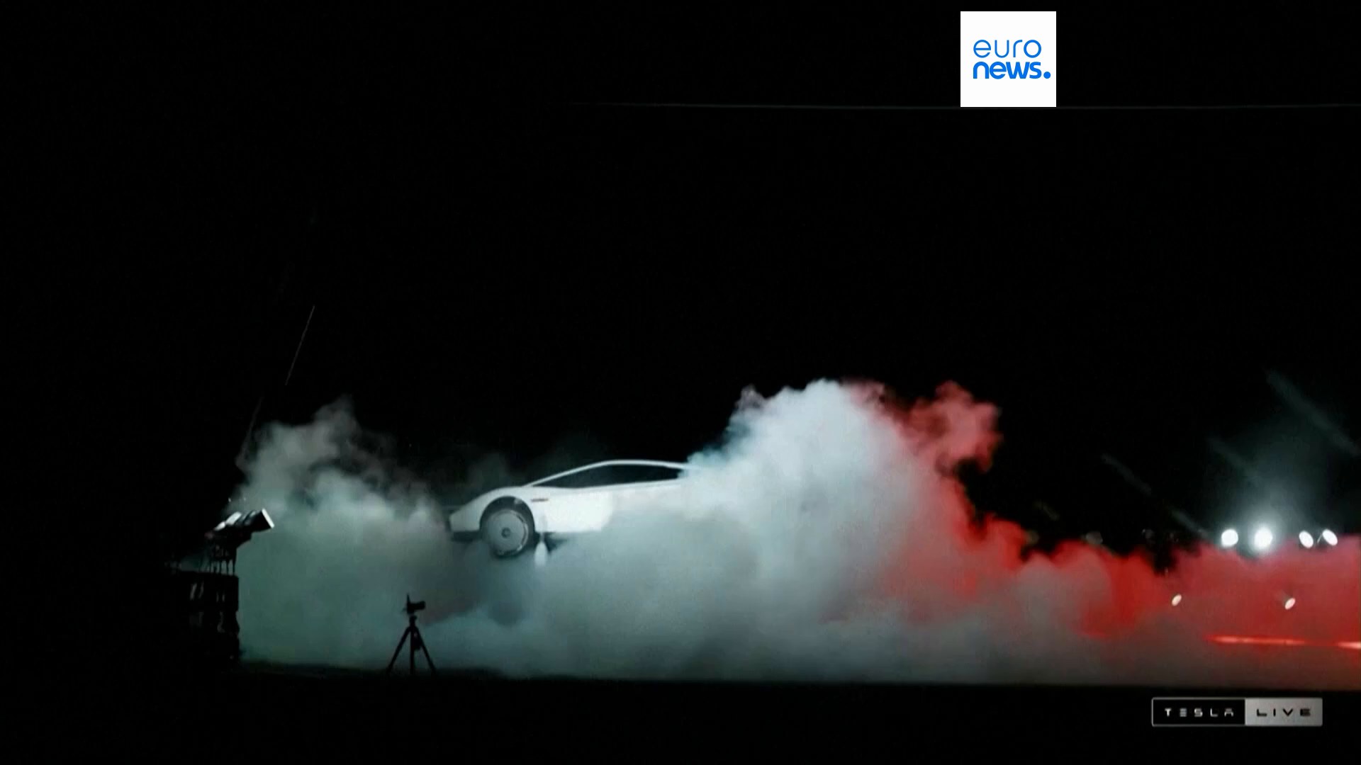
Limits of the evidence: The live frames in this section illustrate the visible actions in the public demonstration; they are not independent tests or proof of production-vehicle capability. Mist obscures the scene, so the precise instant of touchdown cannot be confirmed from the images alone. Nor can the demonstration car, static display car and future customer cars be assumed to share the same internal configuration. The following sections use public interviews, patents and explicit assumptions to explain, system by system, what these actions may depend on and their engineering costs.
Key conclusions and scope of the evidence
This report examines the next-generation Roadster unveiled on October 15, 2026. Its most significant development is not a further increase in motor power, but the integration of tire loading, electrical power delivery, underbody suction and short-duration gas thrust into a single vehicle-motion-control problem. It seeks to alter two traditional constraints simultaneously: how much force the tires can transmit to the ground, and whether longitudinal acceleration must come solely through the tires.
The report’s central assessment is that this combination of systems has a clear physical basis and introduces genuine engineering novelty. The launch-stage demonstrations and explanations provide observational clues, but are still insufficient to independently verify the complete test conditions, internal construction and repeatability of the maneuvers. For prospective users, the more important questions are whether a second acceleration run can reproduce the first, whether suction can be maintained over road undulations, whether the car remains easy to control after its stored gas is exhausted, and how it returns to a safe state when a system fails.
This report distinguishes four levels of evidence: physical hardware and public statements; patent disclosure; engineering analysis; and items awaiting verification.
| Evidence level | What it supports | What it does not directly establish |
|---|---|---|
| Physical hardware and public statements | Visible appearance, exhibited components and designs explicitly described in interviews | Hidden dimensions, complete test conditions or identical configurations across all versions |
| Patent disclosure | Component relationships in original drawings, a particular embodiment and design intent | Certain installation in the car, production performance or road certification |
| Engineering analysis | Force, energy and packaging constraints under explicit assumptions | Deriving manufacturer specifications from illustrative parameters |
| Still unverified | Complete vessels and piping, internal consistency across vehicles and repeated measurements | Filling gaps with another vehicle generation or alternative embodiment and treating them as facts |
Original images take precedence over 3D illustrations, and schematic illustrations cannot substitute for engineering drawings. Sources include Tesla’s current product page, Top Gear’s vehicle presentation and public interview transcript, the official description of Hagerty’s engineering interview, MotorTrend’s on-site reporting, original Tesla patent documents and NASA materials. On-site media descriptions, manufacturer targets and patent examples are not elevated to independently measured results. A patent’s application or grant status only describes the nature of the document; it does not establish product adoption or road approval.
Video scope: After 43:24, the Top Gear video moves into a retrospective and drive of the original Roadster, which cannot serve as road-test evidence for the new car. This report uses a public interview transcript with verifiable timestamps and does not claim to have completed an independent driving test of the new vehicle.
Product identity and variant definitions
MotorTrend quotes design chief Franz von Holzhausen describing the new car as a production-intent prototype and reports a 2028 production target. Top Gear’s use of ‘production version’ should not therefore be taken to mean that certification has been completed or deliveries have begun. The table below uses the variant hierarchy that can be confirmed from the official page while preserving differences between media reports.[1][2][3]
| Item | Confirmed information | How to interpret it |
|---|---|---|
| Performance | Official site: two seats, ‘Road ready’; active aerodynamics and fan-generated suction | A road-use positioning statement does not mean certification is complete |
| Thrust | Official site: two seats, ‘Race ready’; adds rear cold-gas propulsion | Do not treat optional gas-thrust assistance as standard across the range |
| Rocket | Official site: one seat, ‘Invite Only’; perimeter propulsion and airborne capability | The official site explicitly states that it is not approved for public-road use |
| Base Roadster | Top Gear also lists a base version | MotorTrend says production is not yet confirmed; excluded from the confirmed sales lineup |
| Acceleration figures | TG: Rocket, 0.59 s [2]; Hagerty: 0.55 s with rollout [9] | Timing definitions differ; the figures cannot be directly compared or combined |
| Battery capacity | Launch materials do not confirm a final value | The 2017 claim of 200 kWh is not carried over |
| Charging time | TG: 15–80% in under 15 minutes; MT: 10–80% in approximately 10–12 minutes | Charge windows and conditions differ; both require complete charging curves |
| Top-speed claims | TG video: 214 mph as the current figure; 330 mph as a subsequent target | Other reports use different figures; do not combine them into a verified top speed |
| Power conversion | 1 MW is approximately 1341 hp or 1360 PS | The media conversion of approximately 1500 hp is inconsistent |
| Official-site applicability notes | Some page specifications apply to Thrust; additional restrictions apply to Rocket and under regional regulations | Check the applicable variant for each item; do not combine them into one car |
Understanding the system through the sports car
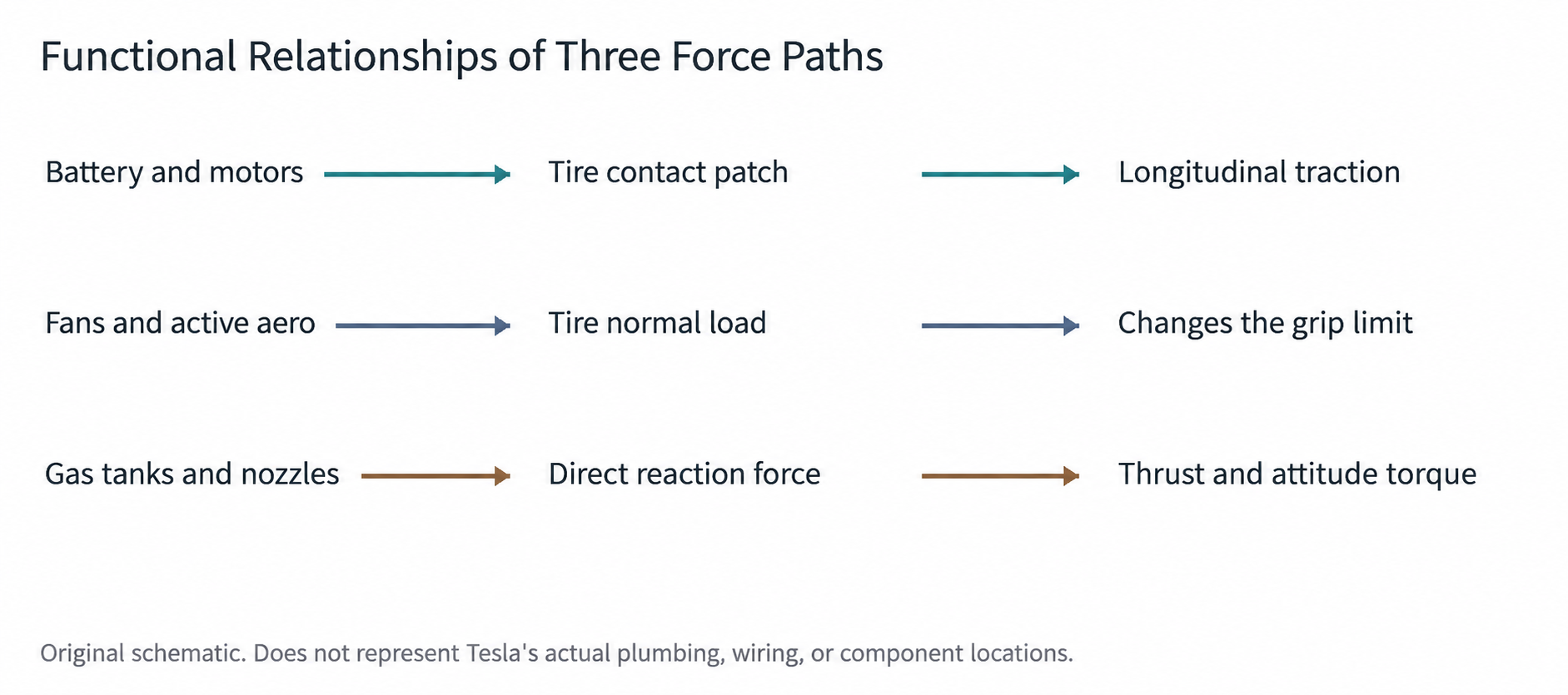
When viewing the new car, the raised rear wing, moving body panels and gas jets are the most immediately eye-catching features. Yet performance is ultimately determined by the connections behind those mechanisms. First and foremost, the vehicle remains an electric car: the battery supplies electrical energy, power electronics convert it into the current the motors require, the motors deliver torque to the wheels through the drivetrain, and the tire–road contact patches transmit force. If any point in that chain reaches its limit, increasing the peak capability elsewhere will not necessarily make the car faster.
This section focuses on the additional vertical load created when fans alter underbody pressure: greater loading on the tires allows them to generate greater longitudinal or lateral force. Exhaust momentum may also produce forces in other directions, whose magnitude must be assessed from the actual flow paths. Cold-gas nozzles, by contrast, expel stored gas in specified directions, applying reaction forces directly to the body. The two cannot simply be added together as a single ‘horsepower’ figure: fans primarily change grip conditions while consuming electrical energy, whereas the cold-gas system’s short-duration external forces and attitude-control moments depend on the gas state and the mass available for discharge.
The most useful way to assess the Roadster is therefore not through one peak figure, but through a set of interconnected quantities: wheel tractive force, normal load, available electrical power, discharge impulse, thermal state and remaining reserves. A launch can concentrate the use of those reserves into less than one second; a circuit lap requires their continual allocation; long-distance travel requires the systems to remain quiet, energy-efficient and unobtrusive to luggage and occupants most of the time. These are three distinct optimization problems facing the same product.
Physical construction and vehicle packaging
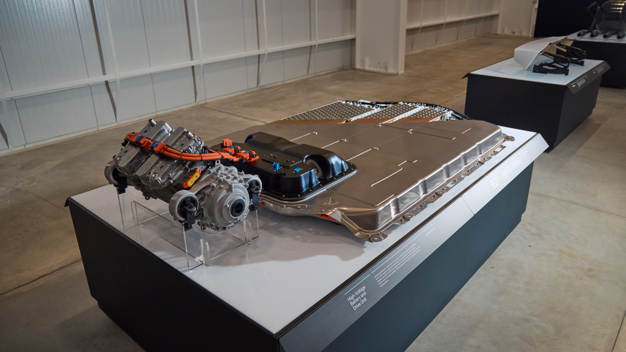
Photographs of the actual vehicle allow its shape and the boundaries of mechanisms to be studied, but a single exterior image cannot establish the complete load-bearing structure. Carbon-fiber exterior panels, a carbon-fiber passenger cell and a carbon-fiber chassis are not synonymous. Confirming the material of one body panel does not establish that the entire vehicle uses a monocoque structure; nor does the material of the battery’s upper cover directly establish that the cover carries crash loads. A genuine product teardown still requires information on load paths, joints, crash structures and repair zones.
Packaging a low-slung sports car requires particularly careful coordination. Occupants want a low seating position; the battery needs thickness, cooling passages and underbody protection; underbody aerodynamics need ground clearance and continuous flow paths. Pushing any one requirement to its extreme often encroaches on another. The adjustment ranges of the seats, pedals and steering controls therefore affect more than comfort: they also determine whether drivers of different builds can remain securely supported under high acceleration, read information promptly and operate the controls precisely.
Patent reference for drive-unit architecture
Vehicle photographs reveal only portions of the housings and connections. The original exploded view in US9692277B2 provides an earlier Tesla integrated electric-drive design that helps explain how a motor, inverter, gearbox and cooling structure can be organized within a housing. It is an integrated assembly with one traction motor, not an actual teardown of the new Roadster’s dual-motor rear axle.[14]
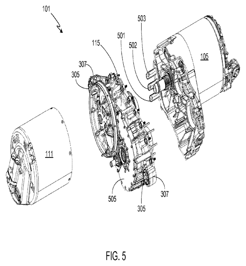
The engineering value of this type of architecture lies in shorter high-voltage connections, consolidated housings and thermal management, and fewer components. The trade-off is closer coupling of thermal, electrical, vibration and serviceability boundaries. A symmetrical housing exterior does not indicate two motors inside, and the direction of an exploded view does not establish the actual assembly or disassembly sequence.
The evidence for the new Roadster’s two rear-axle motors, independent inverters and planetary reduction gearsets remains the named interviews cited above. Two independent torque paths add a degree of freedom for yaw control. Whether they share a housing, how cooling circuits are allocated, and how bearings and half-shafts are installed cannot be filled in using this older patent.
Battery structure and cooling must be distinguished
US11962030B2 discloses an integrated energy-storage structure, with FIG.5 showing the relationship between the battery assembly and additional supports. It provides a technical reference for jointly designing the battery pack and vehicle structure, but does not explicitly identify that configuration as the new Roadster’s battery. It also cannot establish cell dimensions, the number of layers or the share of structural load carried.[15]
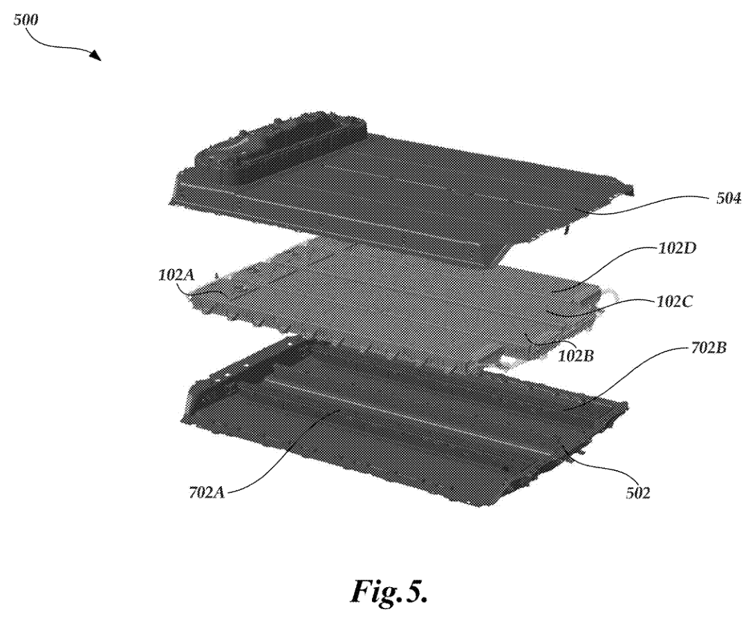
Structural load bearing, impact protection, cell thermal paths and sealing are distinct issues. Using a particular material for the battery’s upper cover does not directly establish that the cover carries the vehicle’s principal loads. Cooling cells from both sides likewise does not directly establish the use of the support and potting layout shown here.
The earlier cell-mounting and cooling-tube design in US9065103B2 and floor-plate heat exchanger in US20140193683A1 show that Tesla has investigated different thermal-management approaches.[16] They cannot replace the interview evidence for two-sided cooling in the new car. The data that would genuinely inform an assessment of the new platform are cell-to-coolant thermal resistance, temperature differences, flow distribution, pressure drop and continuous power, together with whether a fault can be isolated without affecting the entire pack.
Body mechanisms and occupant space
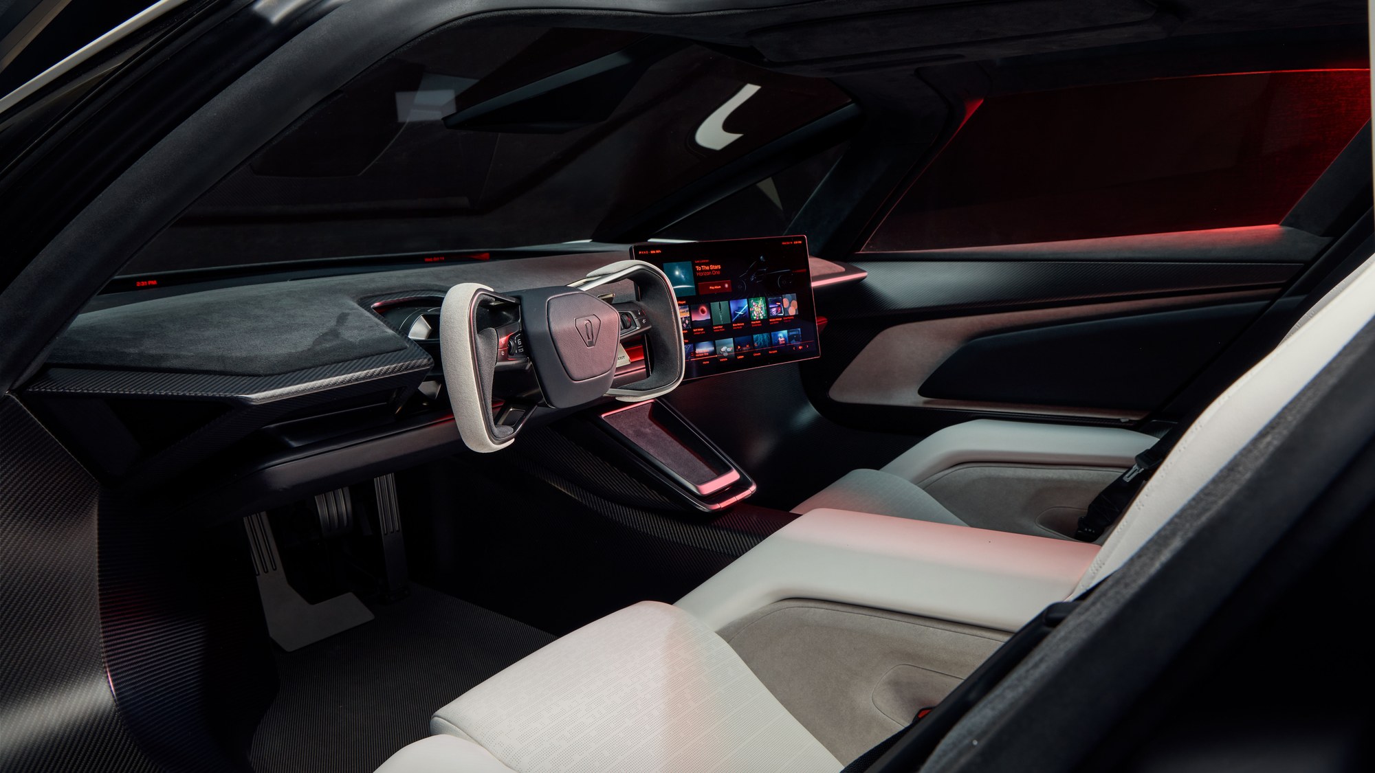
The removable roof is also more than a styling feature. The opening changes the stiffness requirements of the body’s closed sections and introduces issues of sealing, noise, weight and storage. When gas vessels occupy the rear space, whether the original roof-panel storage location remains usable must be confirmed for each variant. For users, ‘the roof can be removed’ and ‘the roof can be carried in the car along with luggage’ are two different capabilities.
The moving rear wing, duct doors and skirts should be regarded as exposed electromechanical systems. They have hinges, actuators, position sensing, seals and wiring harnesses, and are exposed to rainwater, sand and small stones. The smooth body presented at launch shows their retracted state; engineering validation should also cover winter icing, car washes, low-speed scrapes and jamming by foreign objects. If a moving surface becomes stuck, the control system must detect the mismatch, limit performance and prevent asymmetric aerodynamic forces from subjecting the driver to unexpected yaw.
Structural and electric-drive details revealed in interviews
Top Gear’s technical interview provides more specific construction clues than the launch slogans. From 5:09, the engineering lead calls the vehicle in front of him an alpha prototype and discusses the mixed-material structure intended for production. From 6:12, he describes two rear-axle motors, each with its own inverter and planetary reduction gearset, a high-voltage range of 800–1000 V, and cobalt-steel laminations intended to improve power density. These are the engineering team’s design statements, not material or voltage parameters measured for this report.[8]
The battery discussion at 11:44–14:16 emphasizes a nickel-based lithium-ion chemistry tailored for high power, with cooling tubes arranged on both sides of the cylindrical cells. The rationale is clear: shorten the path from heat generation to the coolant, reduce the temperature differences associated with cooling from only one side, and support higher continuous current. Whether the temperature differences are actually reduced, and how long performance can be sustained at different states of charge, still require validation through temperature maps and sustained-power curves. The interview does not provide a precise capacity that can be treated as a final specification.
This is more meaningful than simply describing a ‘more advanced battery.’ Cells optimized for high power may involve a different balance among energy density, service life, cost and cooling complexity; two-sided cooling takes up space and adds flow passages and connections. Its benefits cannot be assessed at cell level alone, but must be evaluated together with pack structure, cooling-pump power consumption and total vehicle mass.
In the powertrain, two independent reduction and inverter paths make left–right wheel-torque control a hardware-level degree of freedom, but their shared battery and thermal management still impose common constraints. If one path is temporarily limited, whole-vehicle control must determine whether the other side can compensate and whether that compensation would introduce yaw. The engineering value of increased power density is to create simultaneous margins in mass, space and sustained output, rather than merely adding peak figures.
How the key components form a complete vehicle
Battery and geometric packaging: MotorTrend’s on-site reporting also mentions 4680 cylindrical cells and a titanium battery-pack upper cover, while the exact capacity has not yet been finally disclosed. This and Top Gear’s description of two-sided cell cooling concern different structural levels: the upper-cover material describes pack construction, while the cooling tubes describe the cells’ thermal paths; neither can substitute for the other. At 16:35, Top Gear reports a wheelbase of approximately 2825 mm; at 5:40, it discusses a weight-reduction target below 1700 kg. The latter cannot be extended into a claim that every configuration has already achieved that curb weight.[3][8]
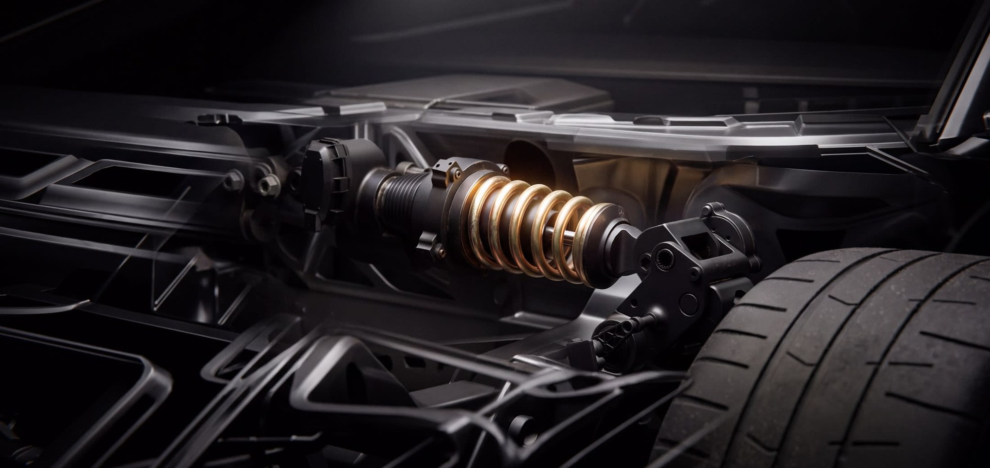
Suspension and ride height: At 39:26–39:42, Top Gear explicitly describes front double wishbones, rockers transmitting motion to transversely mounted adaptive damper assemblies, spool-valve technology and adjustable ride height. This arrangement transfers wheel motion through rockers to spring-and-damper assemblies mounted farther inboard, providing packaging freedom for a low nose and the body surfaces. Specific motion ratios, travel and spring rates are undisclosed, so component shapes alone cannot establish ride comfort or track limits.
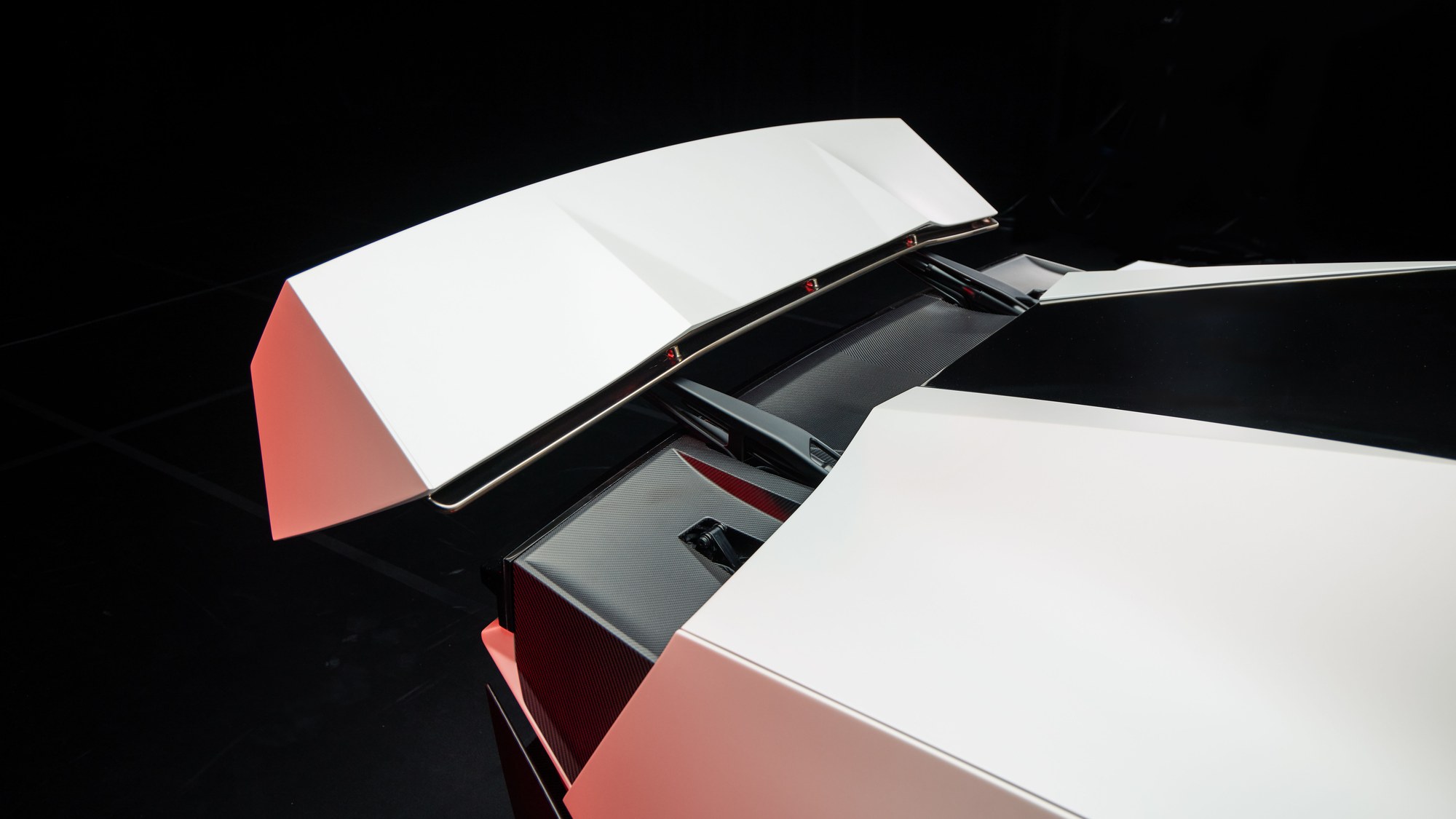
Rear wing and cockpit: The interview at 31:31–31:43 describes four-bar linkages on both sides of the rear wing and two actuators derived from Optimus ankle technology. This explanation of the mechanism in front of the interviewees is insufficient to establish the full quantities of deployment actuators 304 and angle actuators 306 in the patent. At 35:03–35:59, the interview explains the fixed seat bases, manual backrest adjustment, movable pedals and steering controls: prioritizing low weight and a low seating position, and accommodating different leg lengths through pedal adjustment rather than heavy powered sliding mechanisms for the entire seat.[8][13]
Rocket’s space trade-off: At 27:29–27:51, Top Gear’s engineering-team interview describes a Rocket configuration: approximately 400 L of additional vessels occupy the passenger-seat position, combining with the approximately 200 L rear gas-storage system for a total of about 600 L. In addition to four rear propulsion nozzles, there are four nozzles providing upward force and two front nozzles for yaw control, making ten in total. This is the interviewed team’s description of a configuration; it does not confirm that the static display car, the vehicle that performed the demonstration maneuvers and future customer cars have identical internal layouts. Volume is not flight duration, and maneuvers such as rolling require coordinated forces and moments from the complete system; they cannot be attributed to a single pair of nozzles.[8]
Engineering analysis of the vehicle’s space budget
The following are qualitative packaging constraints, not measured drawings or CAD of the new car. A low body must simultaneously accommodate occupants, battery, underbody protection and aerodynamic passages. The rear also concentrates the electric drive, fans, rear-wing mechanism and gas-storage system. Individual systems can be drawn clearly in patents, but integrating them into a complete vehicle requires resolving loads, flow, temperature and service space within the same cross-section.
Longitudinal underbody space: Diffuser ducts require changes in cross-sectional area and relatively smooth bends. If the battery or a crossmember occupies this location, the passage may become narrower or steeper, or need to detour, creating risks of flow separation and pressure loss. Conversely, leaving space for a duct affects battery packaging and structural continuity. Without an actual cross-section, it cannot be asserted that the battery must sit above or below the duct, or incorporate a particular cutout.
Lateral space at the rear axle: Motors, reduction gearsets, half-shafts and suspension each require their own motion and load-bearing envelopes; rear fans also need inlet and outlet areas, mounting brackets and protection against foreign objects. The four fans in patent FIG.2 belong to an embodiment; the number on an actual vehicle must be checked separately against photographs of that vehicle. Neither type of evidence establishes the spacing between electric-drive units. The question to verify is whether the suspension’s full-travel envelope, duct cross-sections and crash structures can coexist.
Gas-storage system space: The approximately 200 L cited in the interview refers to the vessels’ nominal internal volume, not a claim that the entire system occupies only 0.2 m³. Vessel walls and ends, mounting and protective structures, valves and piping, inspection access and crash clearances also need space. The description of approximately 400 L replacing the Rocket’s passenger seat indicates a direct trade-off between seating and stored gas, but is insufficient to quantify the net usable luggage space in other variants.
Thermal and service space: The electric drive, battery and power electronics need heat rejection, fans need continuous airflow, and gas vessels have charging and discharge operating limits. Placing outlets close together may simplify packaging, but may also cause hot-air recirculation between systems or unfavorable pressure differences. These are risks proposed for testing, not assertions that the actual vehicle already has a particular defect.
The most valuable questions to ask of a structural drawing are therefore: what is the cross-section of each passage, what is the swept envelope of each moving part, and where is the isolation boundary for each failure? Without public dimensions, these questions should remain open rather than allowing a visually coherent 3D image to conceal what is unknown.
Fan suction and active aerodynamics
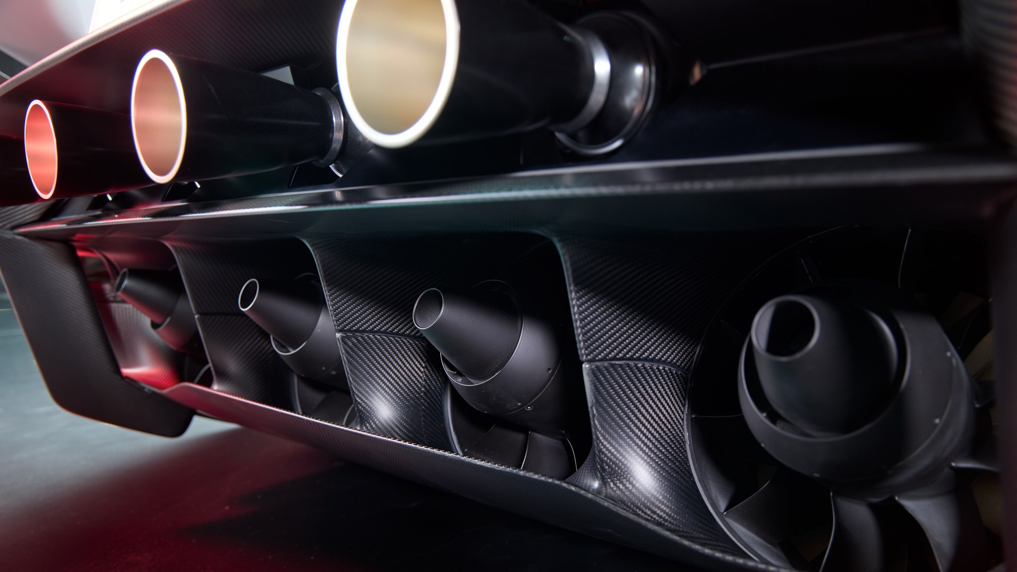
Downforce from conventional aerodynamic surfaces grows approximately with the square of speed and provides limited help at launch. Extracting air from beneath the car and reducing skirt leakage can establish a pressure difference independent of vehicle speed. The simplified relationship is D≈Δp×A: assuming an effective sealed area of 3 m², generating 30 kN of suction force requires only approximately 10 kPa of pressure difference, roughly one-tenth of an atmosphere. Both the area and force here are calculation inputs, not figures published by Tesla.
The engineering challenges lie in leakage and failure behavior. Curbs, potholes, joints, standing water and body pitch all change the gap; if the seal suddenly fails, downforce cannot be guaranteed to decrease smoothly. The controller must combine underfloor pressure, ride height, attitude and wheel-speed data to reduce wheel torque and adjust braking and suspension promptly, preventing a loss of margin while the driver still expects high grip. High suction loads are also transmitted to the tires, wheel rims, bearings, suspension and body; a stronger floor alone cannot address them.
Fans do not provide free grip. The fluid power imparted to the air is approximately Δp_fan×Q; input power can be estimated as P_in≈Δp_fan×Q/η. Here, Δp_fan is the fan’s total pressure rise, including flow-path losses, and does not inherently equal the effective underfloor pressure difference discussed above. For an illustrative total pressure rise of 10 kPa, a flow rate of 5 m³/s and an overall electrical-to-air efficiency of 60%, approximately 83 kW is required; 20 minutes of continuous operation would consume approximately 28 kWh. This is not a Roadster power-consumption prediction. It illustrates why range cannot be back-calculated from downforce without knowing flow rate, pressure losses and efficiency. Gravel, rainwater, noise and wear also require validation.
The patented underbody extraction path
US12746987B1, Electric Fan Car, describes underbody inlet 13, internal air passage 12, rear outlet 14 and electric ducted fan 10. Inclined plate 11 is a separate diffuser, not internal air passage 12. The fan extracts air from beneath the vehicle and discharges it at the rear, enabling active underbody-pressure control even at low speed; an embodiment can be powered by the traction battery.[11]
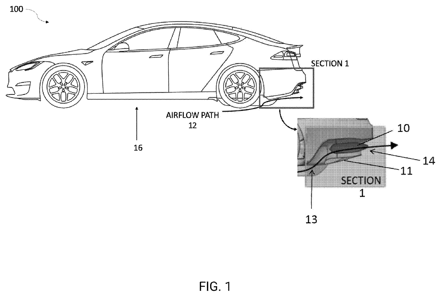
A diffuser is not simply a ‘suction pipe.’ The text explains that the outlet cross-section may be larger than the inlet, allowing airflow to expand and slow within the passage to improve the transition between high-speed underbody flow and the lower-speed environment behind the car. The fan and diffusion process jointly affect pressure and flow rate; fan speed alone still cannot determine total vehicle downforce.
Inlet position determines which underbody region is evacuated. In FIG.3A, low-pressure region 17 lies ahead of the inlet; FIG.3B adds side inlets 18 farther rearward to establish a rear low-pressure region and suppress reverse flow drawn forward from the rear of the car into the central inlet. The side inlets are not intended to supply independent cooling air to the fans. Whether they achieve the intended effect still requires flow-field validation.
A 3D interpretation of the electric fans and diffuser duct
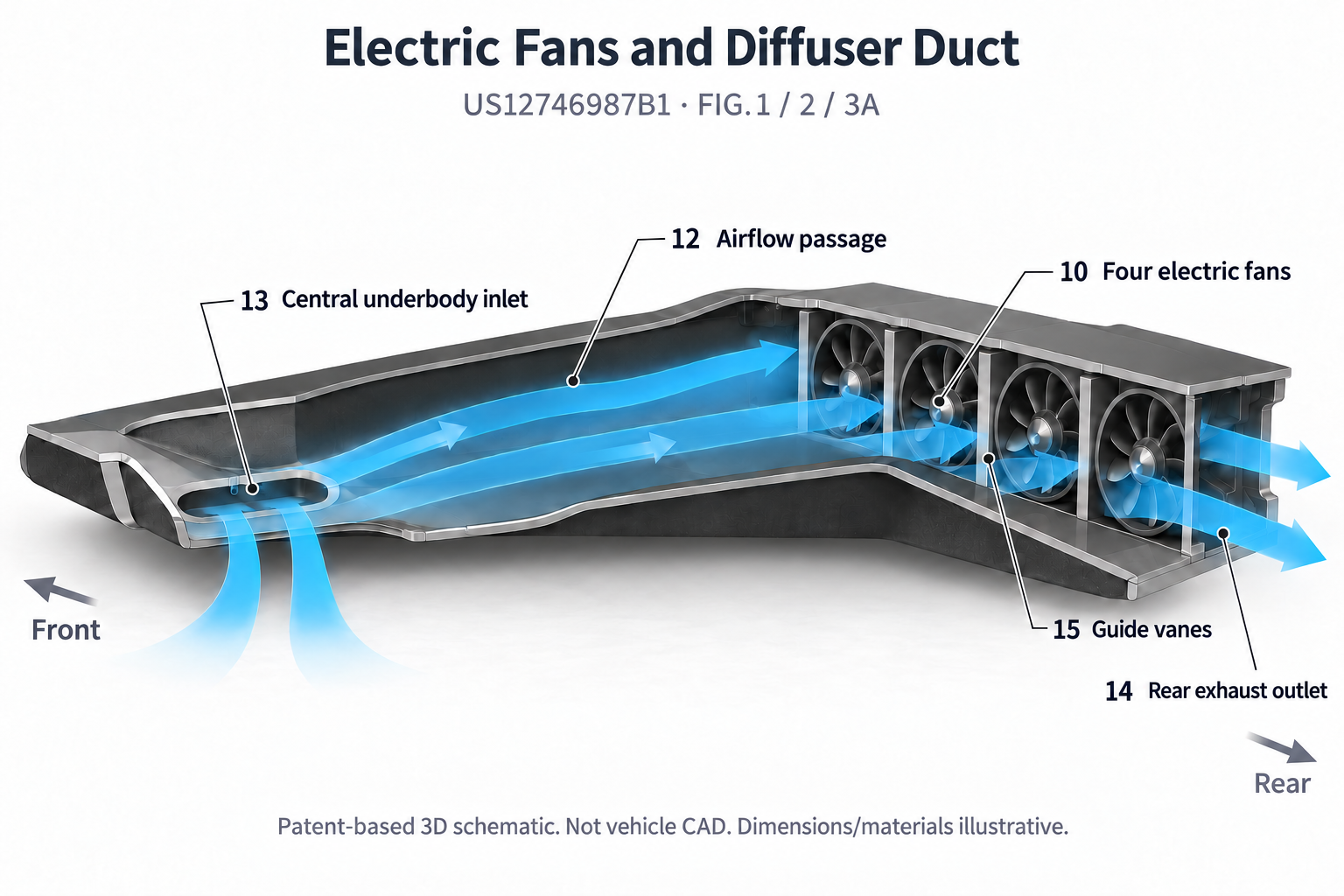
Read the illustration from the central underbody inlet through the rearward diffuser passage, ducted fans and rear exhaust outlet. Outlet guide vanes 15 straighten or control the discharge; their exact dimensions and blade shapes cannot be established from the patent. Housing thickness, curved surfaces and cutaway locations in the schematic are visual devices, not manufacturing data.
FIG.2 shows four fans and three guide vanes, but the specification also permits other fan counts. The side inlets in FIG.3B may either share an air passage with the central inlet or use separate passages and subsets of fans. These two arrangements should be analyzed separately, rather than drawing every passage as though it were known to exist on the actual car.
Engineering analysis must distinguish total airflow from the flow that effectively passes through the intended low-pressure region. Recirculation from the rear consumes fan capacity without delivering equivalent benefit. In a split-path arrangement, an outer fan failure could reopen a reverse-flow path; in a shared duct, a stopped fan and the common outlet could also become leakage paths. These are failure scenarios requiring validation, not problems the patent has demonstrated to be solved. The patent also allows embodiments without ground-contact skirts.
How variable skirts change pressure regions
The adaptive ground-effect system in US12377920B1 treats fans, airflow passages and variable skirts as a coordinated system. FIG.1 includes fan assembly 102, central passage 104, outer passages 106, side skirts 108 and front skirt 110; central portion 112 and outer portions 114 of the front skirt are distinct regions.[12]
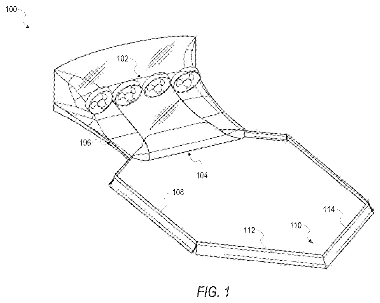
The purpose is not simply to seal the entire underbody, but to change where air enters, which regions develop pressure differences and how those differences are distributed. In the relevant description, outer passages 106 lie outside the region defined by the side skirts; they should not be interpreted as another central suction pipe inside the sealed chamber. The illustration supports distinct airflow roles, but provides no production dimensions.
This expands the control objective from ‘maximum downforce’ to both downforce and aerodynamic balance. If the center of pressure moves too far rearward, the front tires may no longer retain sufficient steering reserve; if the gap suddenly increases on one side, left-to-right loads may also change. Sensing, control inputs and adjustable mechanisms are patent design options, not evidence that every type of hardware is installed on the actual car.
A 3D interpretation of variable skirts and their practical costs
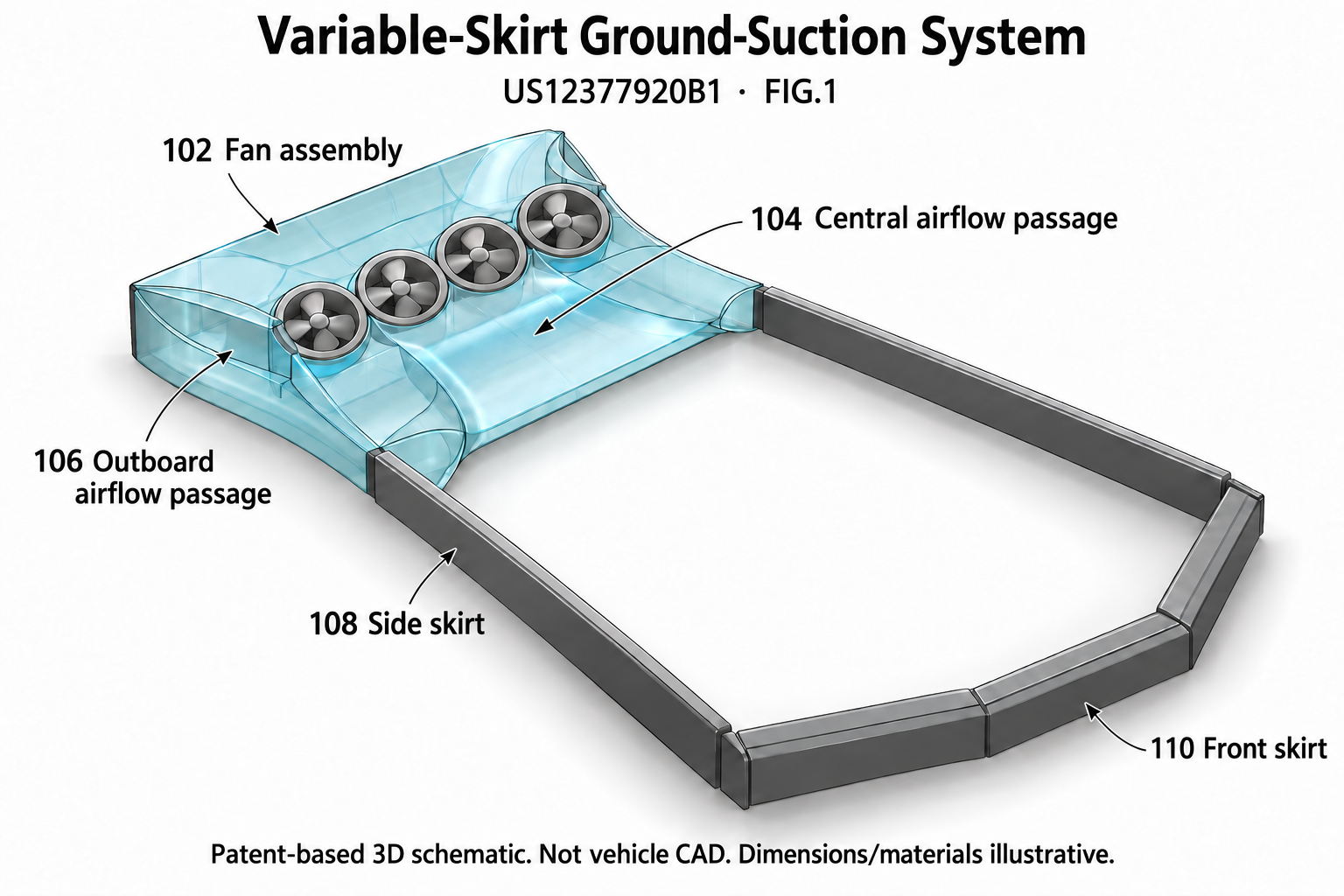
In the illustration, side and front skirts enclose the active region, while rear central and outer passages lead to the fan assembly. It helps explain how components sit relative to one another; it cannot reveal ground clearance, seal contact force, actual panel thickness, floor load capacity or manufacturing details of the actuation mechanisms.
In the patent’s first mode, the side, front and rear skirts may be deployed, using primarily the central fans to establish a higher pressure difference at a lower mass flow rate. In the second mode, the side skirts may remain in place while the front and rear skirts lift and both central and outer fans operate, increasing throughflow. The skirts may also maintain a controlled gap close to the ground rather than continuously rubbing against it.
The two modes change the fans’ operating points: impeller characteristics and flow-path resistance jointly determine flow rate, pressure rise and efficiency. Better sealing generally reduces leakage at the target pressure difference, but does not guarantee stable, efficient operation at arbitrarily low flow rates. Stall margin, current limits and speed limits must be checked; neither mode can simply be assumed to consume less power in all cases.
Control logic for zoned pressure and degraded operation
In US12377920B1 FIG.2, central skirt 212 divides the underbody into regions 208 and 210, connected to fan assembly 202 through passages 204 and 206; optional divider 214 can further separate the flow paths. FIG.3 uses different passages and deployable skirts to alter front-to-rear downforce distribution. These are additional embodiments, not evidence that the actual car uses all of the zoning arrangements simultaneously.[12]
Pressure distribution matters more than the total alone. If the front seal or a seal on one side opens, movement of the center of pressure may produce substantial pitch, roll and yaw responses even if total downforce falls only slightly. When multiple fans share a sealing boundary that has already failed, increasing their speed may not restore the original load distribution; redundancy in fan count does not automatically provide aerodynamic-function redundancy.
Patent FIG.4 sets out operating-condition detection 402, skirt configuration 404, fan activation 406 and continuous monitoring and adjustment 408. FIG.5 includes state machine 514 with hysteresis, predictive component 518, pressure monitoring 538, performance monitoring 540 that tracks fan current and skirt-position accuracy, and fault detection 542. These describe a control-architecture concept, not an actual vehicle sensor inventory or proof of safety coverage.
Engineering analysis: Hysteresis can prevent repeated opening and closing near switching thresholds. Position feedback should be cross-checked against pressure feedback: if commanded and actual positions agree but pressure difference is insufficient, seal wear, reverse flow or a fan limitation may be responsible. An abnormal relationship between current and pressure at similar fan speeds may indicate blockage, foreign objects or a changed flow path. Specific diagnostic thresholds must be established through vehicle testing.
A failure strategy cannot simply say ‘switch everything off.’ Abruptly removing additional load during a high-speed corner may itself worsen stability. Torque, braking, ride height, wing angle and remaining suction capacity must be coordinated so that tire demand decreases with available load, while clear performance limits are communicated to the driver. This is a safety-design requirement, not a strategy this report confirms Tesla has implemented.
The same principle applies to power allocation. If the fans and traction motors share a battery, they also share peak-current and thermal constraints; suction increases grip but consumes electrical power otherwise available for propulsion. Additional suction is more likely to provide sufficient marginal benefit when the operating condition is limited by traction or stability margin. Maximum wing angle, maximum fan power and maximum wheel output cannot be assumed to be simultaneously sustainable.
How dual-mode underbody flow switches
At 18:34–19:20, the Top Gear interview describes a dual-mode concept: at low speed, skirts and suction supplement the downforce that conventional aerodynamic surfaces cannot yet generate in significant amounts; at higher speed, the front and rear skirts lift, increasing underbody airflow while the fans continue extracting air. The side skirts and front and rear skirts do not always remain in the same state.[8] US12377920B1 discloses various embodiments involving front-skirt movement and zoned control. The interview’s description can be considered alongside these patent concepts, but this does not establish every moving part, sensor and airflow path as actual vehicle equipment.[12]
Switching control involves more than ‘fans on or off.’ During the transition from low-speed sealed suction to high-speed throughflow, the center of pressure, flow demand and sensitivity to ride height may all change. The decision to switch must consider actual pressure and stability margin, rather than relying solely on an unvalidated fixed vehicle-speed threshold. US12746987B1 permits embodiments without ground-contact skirts, so its diffuser duct cannot simply be combined into an assumed sealed-suction chassis. The two patents describe design possibilities for ducting and sealing control, respectively.[11][12]
Body pitch, rear-wing angle of attack, fan output and suspension height must work together. At 29:08–31:43, the interview links front movable aero surfaces, cooling outlets, wheel-arch pressure relief and the rear wing, and explains the reuse of actuator technology.[8] The following sections distinguish the visible mechanism in the rear-wing patent from its control degrees of freedom. Reused technology must still be validated for vehicle vibration, impacts, water and dust, sustained aerodynamic loading and failure conditions; it cannot substitute for complete-vehicle testing.
The active rear wing’s two degrees of motion
US20260285418A1 is a published patent application. Its FIG.3 embodiment uses four-bar linkages on both sides to deploy multi-element wing 104 upward and rearward, with a separate angle drive changing the orientation of the complete wing assembly. The two motions can be coordinated and need not occur in a prescribed sequence. A flow-guiding slot 302 forms between main wing 106 and leading-edge slat 108; 108 is a leading-edge slat, not a trailing-edge flap.[13]
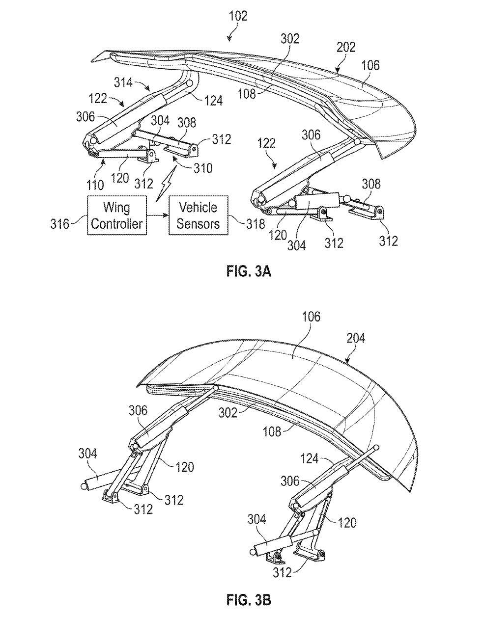
Each side’s four-bar linkage consists of first link 120, second link 308, support arm 124 and frame 310. Deployment actuator 304 changes the mechanism’s position, while angle actuator 306, concealed within the support arm, adjusts the angle of the complete wing assembly. Distinguishing position from angle of attack explains how stowage, downforce and low-drag modes can be accommodated.
The linear guide in FIG.4 and rotating lead screw in FIG.5 are alternative arrangements and must not be superimposed onto FIG.3. The patent drawings provide neither complete manufacturing dimensions and tolerances nor hinge life or actual vehicle attachment strength. Nor can the number of actuators in the drawings establish that the hardware shown in the interview necessarily has the same configuration.
A 3D interpretation of the active rear wing and its load paths
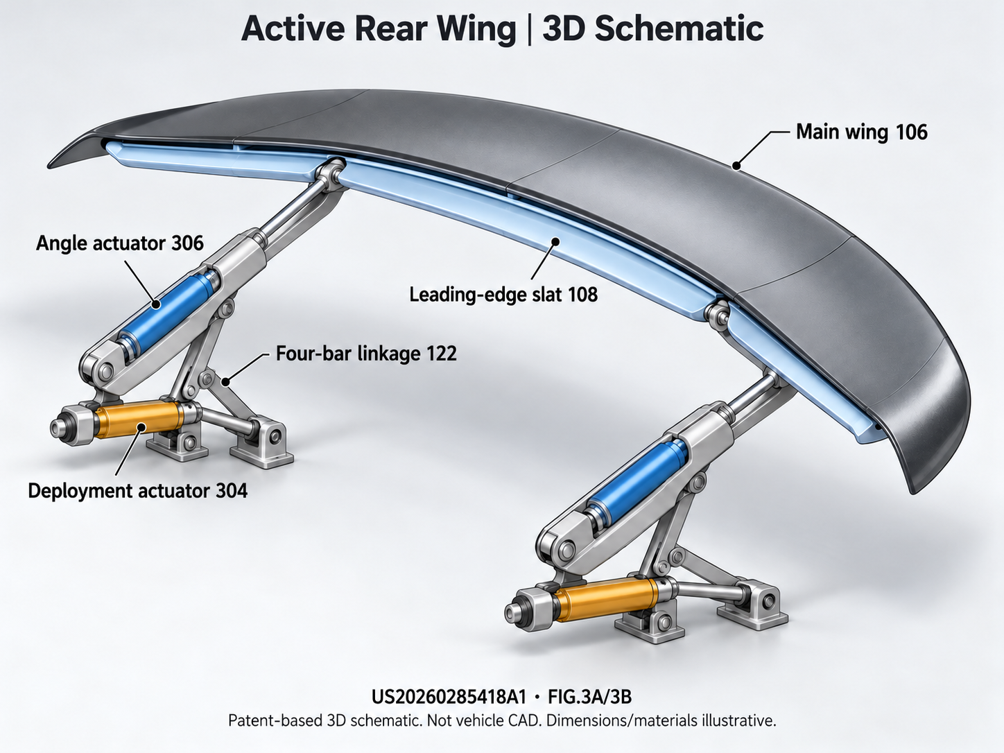
Deployment places the rear wing in an effective incoming airflow and working position, while angle adjustment changes aerodynamic force and drag. The patent describes maintaining the relationship between wing elements as the complete multi-element assembly rotates. The curved wraparound ends of the main wing relate to the rear-body contour in the retracted state, but the schematic cannot prove that a particular road car uses the same surfaces or gaps.
Aerodynamic loads pass from the wing surfaces through the support arms, links and frame into the body. Laterally asymmetric loading, synchronization errors between mechanisms and high-speed vibration all affect bearings, pivots and control accuracy. Appropriate validation should cover loads across the full operating range, reverse-direction impacts, jamming and position-feedback failures, rather than merely measuring deployment speed.
The original text’s 3–15 mm gap, deployment in less than 3 seconds, angle adjustment in less than 0.25 seconds and high-downforce figures all describe embodiments, not validated Roadster specifications. Non-backdrivable mechanisms hold position under normal aerodynamic loads and reduce holding power consumption; mechanical release above a limit provides a separate yielding condition. Together, these do not imply rigid locking during an impact. Passive release and active or anticipatory retraction remain descriptions of safety concepts; they must not be filled in as known latch or clutch structures or treated as crash certification.
Forces and energy in extreme acceleration
60 mph is 96.56 km/h, or 26.82 m/s, not 100 km/h. If timing begins from true rest, reaching 60 mph in 0.59 seconds requires an average longitudinal acceleration of 45.46 m/s², or 4.64g. In a constant-acceleration example, the distance traveled is just 7.91 m; the actual distance depends on the acceleration curve. It is also essential to verify whether a one-foot rollout is deducted, along with gradient, wind speed, surface preparation, tires and initial battery state of charge. Extremely short times cannot be ranked directly across different timing protocols.
The following calculations consistently assume an instantaneous mass of approximately 2,000 kg for the vehicle, driver and gas together; this is not a claim about the new car’s curb weight. Neglecting low-speed resistance and short-term mass change gives an average net external force of approximately 90.9 kN. Assuming all tires can be used effectively and a friction coefficient of μ=1.5, relying on tires alone requires a total normal force of approximately 60.6 kN. After subtracting gravity, approximately 41.0 kN of additional downforce is required, equivalent to approximately 4.2 metric tons-force. This is an idealized lower bound. With rear-wheel drive, only the rear tires’ normal load is available, so axle-load transfer, the aerodynamic center and rear-tire load sensitivity must all be included; simply adding all vehicle loads together is not a complete calculation.
Another way to view this: if suction downforce equals exactly twice the vehicle’s weight, the idealized example with all wheels effectively utilized and μ=1.5 gives a traction limit of 4.5mg, still slightly below 4.64mg. Tire μ is not constant, and doubling load does not mean doubling grip. The value of gas thrust is precisely that it provides a direct force independent of tire contact, rather than magically increasing rubber friction.
Translational kinetic energy at 60 mph is approximately 719 kJ, or 0.200 kWh; dividing by 0.59 seconds gives an average net mechanical power of approximately 1.22 MW. With constant acceleration, instantaneous power at the endpoint is approximately 2.44 MW. This is the mechanical power delivered to the vehicle by all propulsion channels together; it must not be used to assert that the motors must produce 2.44 MW. Energy previously stored in the gas vessels can be released rapidly, and the motors provide only part of the total force.
Thus, ‘how much electricity does one launch consume?’ and ‘can the system deliver this much power?’ are separate questions. 0.2 kWh is little kinetic energy, but delivering it in less than a second is difficult. Seats, restraint systems, head and neck support, and control of the rate at which acceleration builds are equally important. 4.64g is an average longitudinal value, not a human safety threshold, and it cannot establish that ordinary road-car occupants can safely withstand every maneuver.
The actual components of cold-gas propulsion
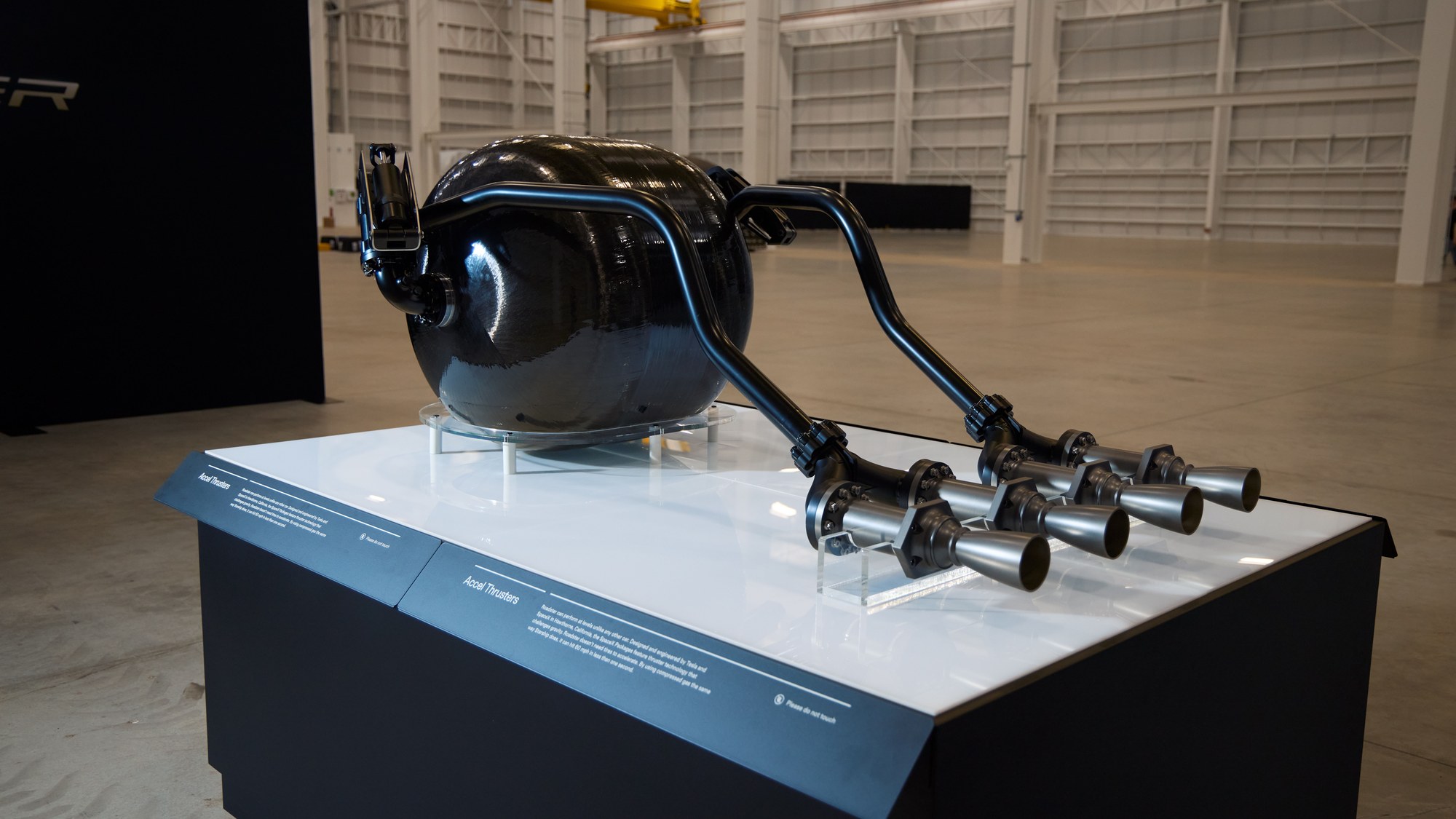
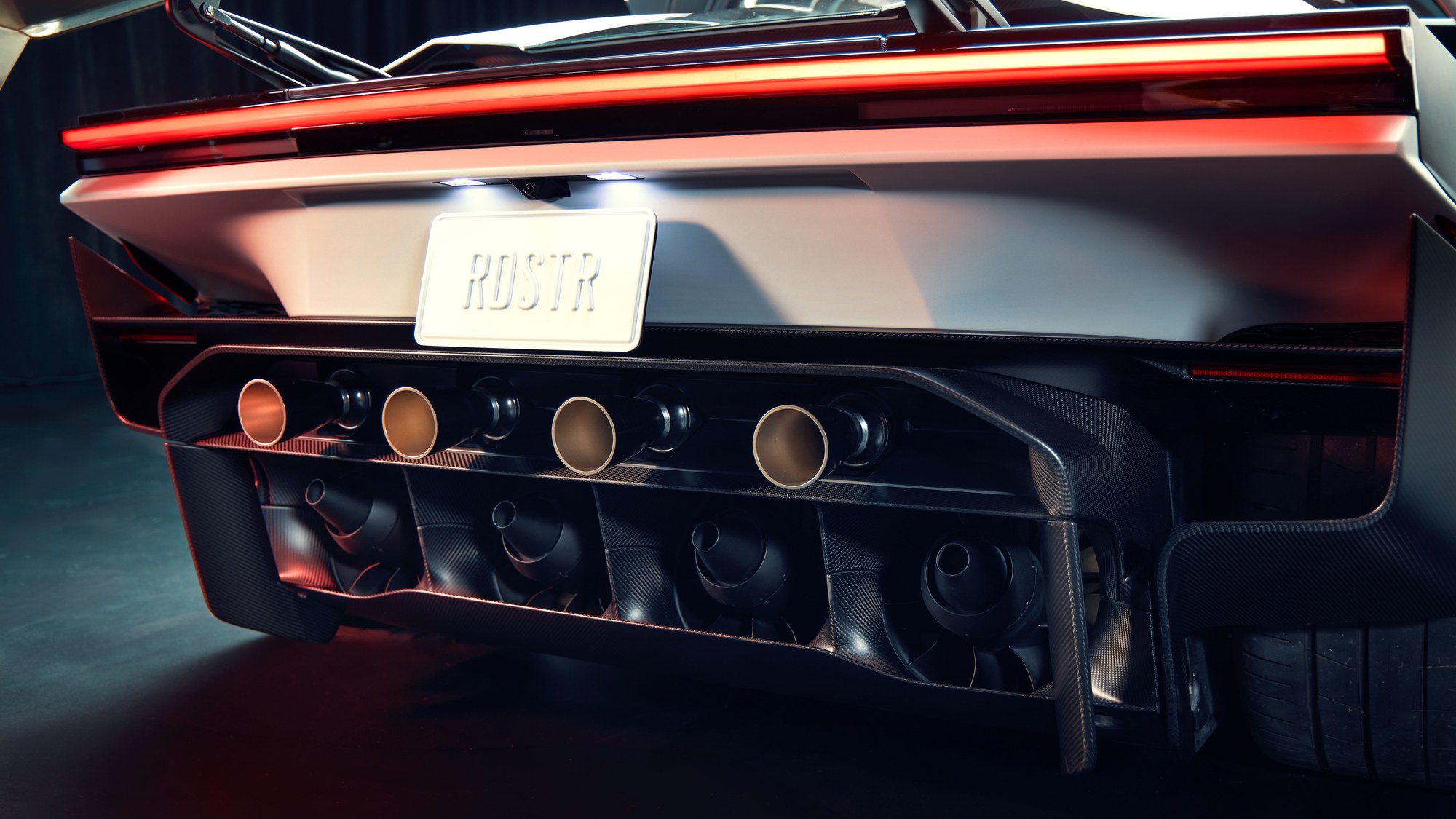
The displayed hardware in the photograph reveals the relative arrangement of components, but the image cannot establish vessel wall thickness, operating pressure, valve response time or crash mounting loads. Among the patent materials reviewed for this report, no verifiable patent covering the new Roadster’s cold-gas vessels and complete piping system was obtained; this does not assert that no related application exists. The piping descriptions below remain attributed to interviews and displayed hardware. Fan, skirt or rear-wing patents cannot be borrowed to fill in hidden structures.
At 20:42–23:26, Top Gear’s explanation connects the hardware with its operating conditions: approximately 200 L of composite-overwrapped pressure vessels in the rear compartment, replenished with high-pressure nitrogen from an external source, and valves connected to the rear nozzles by equal-length piping. At the time, the engineering team quoted a refill time of 2–6 hours, with less than half an hour still a development target. One fill supports only one high-intensity burst of the type described, quoted at 22:59 as approximately five seconds. This does not mean the entire vehicle can operate for only five seconds, nor does it describe Rocket’s flight endurance. It cannot be extrapolated into five one-second launches, since pressure decay and total impulse also impose limits. This affects practicality more directly than the ability to ‘accelerate instantly.’[8]
Orders of magnitude for thrust and impulse
Cold-gas propulsion produces a reaction force through the expansion and discharge of stored gas, without requiring combustion. The full thrust equation includes both a mass-flow term and a nozzle-exit pressure term; for an order-of-magnitude estimate, these can be combined into an effective exhaust velocity vₑ, giving F≈ṁvₑ and total impulse J≈m_gas vₑ. These relationships come from standard propulsion mechanics (the NASA thrust equation and specific-impulse definitions [4][5]), not a Tesla-specific model.
Continuing with the 2-metric-ton vehicle example, the net momentum change required for 0–60 mph is approximately 53.6 kN·s. If the tires contribute an average of 30 kN over 0.59 seconds, the gas jets must deliver approximately 35.9 kN·s of additional impulse. Solely to illustrate sensitivity, assuming an effective exhaust velocity of 500–700 m/s gives gas consumption of approximately 51–72 kg. Relying entirely on gas thrust would require approximately 77–107 kg. Exhaust velocity is an analytical assumption, not a measured Roadster parameter. The result depends on the gas, temperature, jet expansion, vessel-pressure decay and actual wheel force.
This also shows why ‘200 L’ or ‘600 L’ alone does not determine usable impulse. Beyond volume, the filling state, temperature, gas properties and minimum usable pressure must be known. High-pressure gas departs from ideal-gas behavior; one cannot casually assign a pressure and then treat the resulting mass as an official specification. The mass of the vessels and protective structures must also be included.
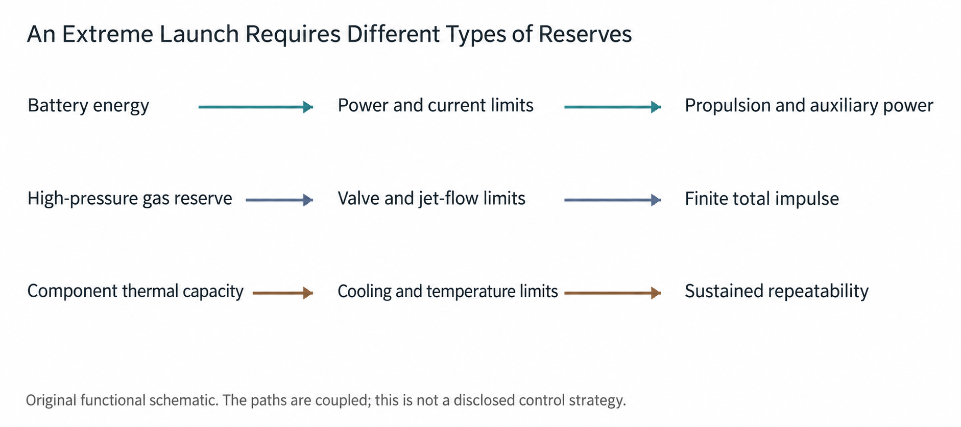
High-pressure vessels and actuators
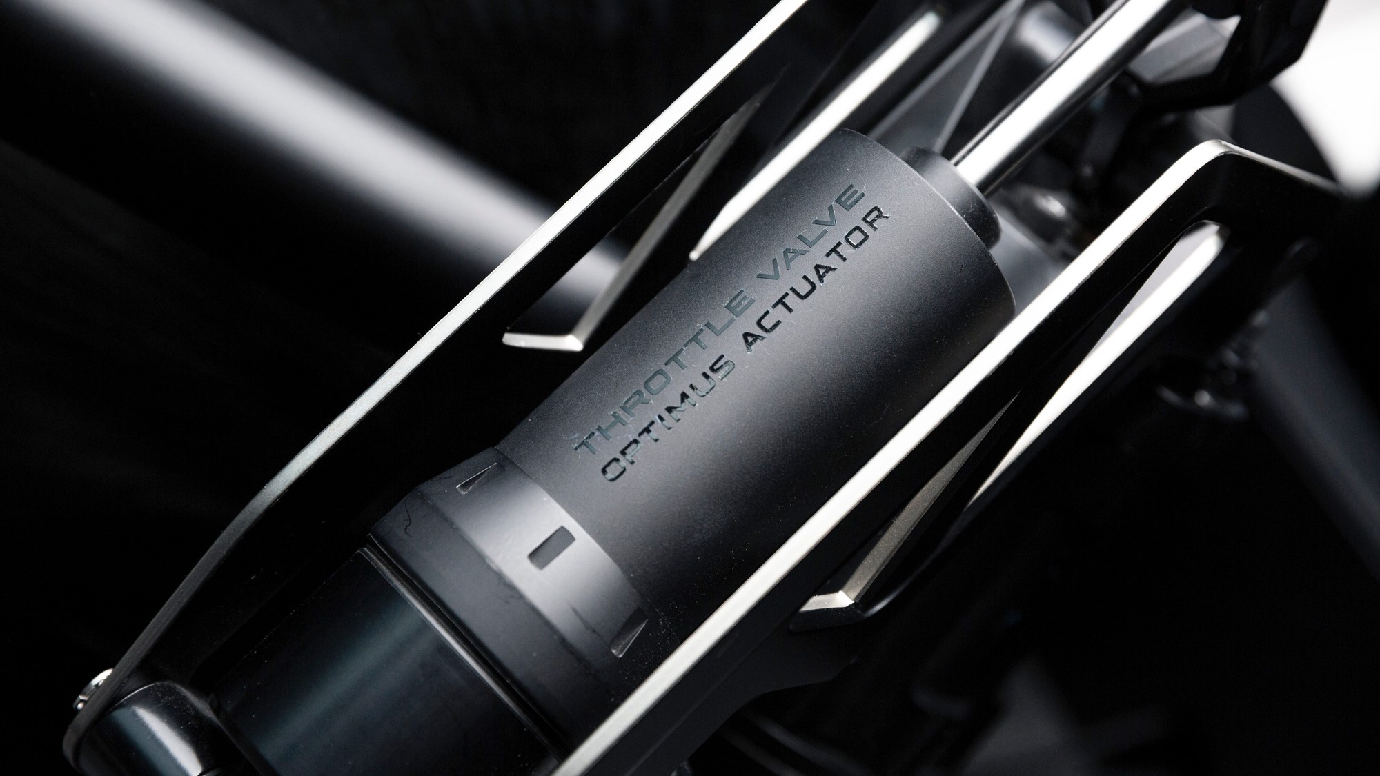
At 21:26–22:16, Top Gear’s component explanation states that the vessel outlet connects to a valve, an actuator regulates its opening, and gas reaches the rear nozzles through equal-length piping. Each nozzle can be controlled separately to maintain a straight path or apply yaw correction. In the terms of this interview segment, the described system uses externally replenished nitrogen as its working fluid; this is not a universal confirmation covering every prototype, version or delivery specification. What is reused is actuator capability; it must not be interpreted to mean that an electric fan directly produces equivalent gas-jet impulse.[8]
For the valves, the key metrics are response speed under large pressure differences, flow controllability, reliable closure and cycle life. Equal-length piping facilitates consistent control, but does not automatically eliminate pressure changes, gas-temperature differences or valve lag. For the vehicle, the critical issue is whether left and right thrust build and cease as intended, particularly during an extremely short launch or an airborne maneuver.
Composite-overwrapped pressure vessels typically use a liner to maintain gas tightness, with the outer fibers carrying the principal pressure loads. NASA’s damage-tolerance guidance emphasizes initial flaws, load spectra, nondestructive inspection and crack growth under sustained loading. Aerospace methods are not automotive certification rules, but they show why neither a single demonstration nor a single strength test establishes long-term service life.[10]
Gas inventory and airborne control
Flight makes the inventory constraint even clearer. Hovering a 2-metric-ton vehicle for one second requires approximately 19.6 kN·s of impulse just to counteract gravity; in the same 500–700 m/s example, that consumes approximately 28–39 kg of gas. Takeoff acceleration, attitude corrections, lateral movement and deceleration for landing are additional. A short hop may include a ballistic phase during which gravity need not be continuously offset in full, so ‘several seconds airborne’ cannot automatically be equated with ‘several seconds hovering.’ Conversely, a roll and a landing do not demonstrate sustained flight, redundant landing capability or suitability for everyday aerial transportation.
For control, attitude moments depend on thrust and the distance from its point of application to the center of gravity; mass and inertia also change as gas is released. The system must simultaneously meet position, angular-velocity and landing-attitude requirements within a limited gas budget, while retaining fault margin. Once ground contact is lost, tire steering and tire braking can no longer recover the situation. A delayed valve, inconsistent nozzle thrust or a sensor error can escalate from a drivability issue to an attitude-safety issue.
Battery drive and sustained heat rejection
Battery capacity answers the question of how much energy is carried; power capability answers how quickly that energy can be delivered. A car may have a large battery, yet its output can still be limited by internal resistance, DC bus current, the inverter and cooling capacity. Conversely, a battery with very high short-duration power is not necessarily well suited to energy-intensive long-distance driving. For the new Roadster, capacity, usable capacity, peak discharge power and continuous discharge power should be considered separately.
A twin-rear-motor layout allows independent control of the driving force at the left and right rear wheels. Fast motor response makes it easier to adjust the torque difference between the wheels, but the capability remains limited by tire contact conditions. Software cannot create grip where one side of the road is wet or uneven. Independent rear-axle control is valuable because it distributes force more precisely within the available limits while coordinating with braking and front-wheel steering. It also requires accurate estimates of vehicle sideslip, tire slip and road conditions.
Rear-wheel drive and all-wheel drive face different launch conditions. Acceleration transfers load to the rear axle, helping rear-wheel traction while unloading the front wheels. To maintain directional stability during an extremely rapid launch, the system must prevent excessive front-wheel unloading from compromising control. Underbody suction could change this balance if it generates sufficient load at low speed. However, the location of the suction load and its front-to-rear distribution matter as much as total downforce.
Energy losses occur as electricity flows through cells, busbars, contactors, inverters and motors. The total energy used by one extremely short launch may be modest, yet instantaneous current and local heat flux can be very high. Over ten consecutive launches, the question changes from whether one peak can be delivered to whether heat can leave critical components quickly enough. Thermal controls may allow the first run to meet the target, then progressively restrict later output as cells, motors or power modules heat up. That is normal engineering behavior, but it must be clearly explained in product information and testing.
Sustained high-speed driving imposes a different burden. Aerodynamic drag increases with the square of speed, while the power required to overcome it rises with the cube. A higher top speed requires more than peak power: tires capable of the speed, aerodynamic stability, reliable bearings and driveline components, continuous heat rejection and a sufficiently long test road are also essential. Brief gas thrust can help accelerate the vehicle, but does not establish that it can continuously overcome drag at high speed.
Assuming 90% efficiency for the complete electric drivetrain, 1 MW of mechanical output implies approximately 111 kW of waste heat, or about 6.7 MJ in one minute. These are illustrative calculations, not measured Roadster efficiency. They show why a short-duration peak must be distinguished from sustained track output. Rapid cold-gas expansion and compression during replenishment also create separate thermal cycles, so valves and seals require durability validation.
Charging targets and travel efficiency
Peak charging power describes only one point on a curve. Actual waiting time depends on average power over the entire charging interval and is affected by initial state of charge, battery temperature, charger capability and power sharing. Without published test conditions, a launch-stage peak cannot be directly converted into the time required for every highway charging stop.
For an illustrative usable capacity of 100 kWh, charging from 10% to 80% adds approximately 70 kWh to the battery. Completing this in 12 minutes requires about 350 kW average battery-side power; in 10 minutes, about 420 kW. A larger battery needs higher average power to cover the same percentage interval in the same time. This is a dimensional consistency check, not an estimate of the new Roadster’s actual capacity or charging capability.
Charger output must also be distinguished from the power actually absorbed by the battery. Cable and conversion losses, together with thermal-management accessory consumption, affect the difference. Fast charging immediately after a hot track session may first be limited by the need to cool the battery; cold conditions may require preheating. A useful test should publish the complete power curve, record ambient temperature and battery preconditioning, and repeat the procedure at different initial states of charge.
Chassis and by-wire systems
By-wire systems allow software to define the relationship between driver inputs and wheel-end actions. A small steering-control movement can command different front-wheel angles at different speeds; a brake-pedal request can coordinate regenerative braking, friction brakes and other means of deceleration. The advantage is that controllers can pursue one shared objective. The challenge is to provide feedback that remains clear, continuous and predictable to the driver.
Digital control does not mean an absence of safeguards, but neither does it establish that adequate safeguards already exist. Validation must address redundant power, communications, sensing and actuation paths, fault-detection times, and the ability to drive after a failure. For a car whose performance depends on multiple active mechanisms, safety objectives must extend beyond individual component reliability. When one component drops out, the other systems must stop relying on invalid performance assumptions.
For example, a sudden reduction in fan output reduces available tire grip. If the motors maintain the previous tractive force, excessive tire slip may result. Appropriate coordination should quickly withdraw torque that depends on the additional vertical load and clearly inform the driver. Unequal left and right rear-nozzle thrust also creates an additional yaw moment that the vehicle must manage. These are engineering requirements to consider, not claims that Tesla has adopted a particular solution.
Braking must likewise be evaluated in terms of energy and durability. When the battery is full, temperatures are abnormal or regeneration is limited, the friction brakes must provide sufficient deceleration. An air-brake wing’s effect changes with speed, while gas-assisted deceleration is limited by stored reserves. A single peak value therefore cannot establish equivalent braking capability under every condition. What drivers most need is consistent pedal response across operating states, rather than knowledge of the force contribution of each actuator.
User value and product tradeoffs
The easiest mistake with this car is to equate a demonstrable capability with an everyday function. Short-distance acceleration and controlled-venue attitude demonstrations provide useful observations. Without complete original records, however, edited footage cannot independently establish timing, mass, loads or the internal control strategy. Wet roads, potholes, loose stones, pedestrians and uncontrolled traffic demand greater safety margins. Usable product performance is generally below the most aggressive demonstration mode.
For road users, the fundamentals are steering, suspension, braking, the cockpit and energy replenishment. Track users should consider lap-time consistency over a continuous session, tire wear and maintenance time. Collectors or technology-demonstration users may find a brief thrust mode attractive in its own right. These three groups can reasonably reach different conclusions about the same vehicle.
The everyday cost of gas-equipped versions cannot be assessed from electricity prices alone. Users also need to know where gas can be replenished, what equipment and qualifications are required, how long filling takes, whether a specified gas and purity are required, how often vessels must be inspected, and what transport or parking restrictions apply. Until these conditions are clear, the approximately five-second burst described in the Top Gear interview remains a statement about the short-duration capability of the 200 L Thrust system, rather than a complete ownership-experience promise.
Airborne demonstrations require even more careful interpretation. Once the vehicle leaves the ground, tires no longer provide lateral or braking forces; control depends on thrust allocation, attitude estimation and remaining gas. Even if brief attitude changes are feasible, that does not establish the range, redundancy, operating environment or legal status of a conventional aircraft. The ability to jump does not imply permission or capability to fly within road traffic.
Public cockpit information describes fixed seats and adjustable pedals or steering controls. Ergonomic claims should be checked by version and direction of adjustment. Media reports also describe a charging-port arrangement that depends on wing deployment. If retained in the delivered product, access to charging after actuator failure must be defined. The suitability of removable wipers and camera-based mirrors also varies by region; clean styling should not obscure the validation required for wet-weather use and regulatory compliance.[1][3]
Innovation and earlier precedents
Fan suction, cold-gas propulsion and by-wire control each have a sound physical basis. The Roadster’s potential innovation lies primarily in integration: assigning roles to motors, chassis, active aerodynamics and nozzles under a shared motion objective, while managing energy and impulse reserves over different timescales. Patents add traceable mechanisms and airflow concepts, but disclosing a design, installing it in a prototype and validating a repeatable product are three different achievements. Technical value must still be demonstrated in the latter two.
McMurtry demonstrated the Spéirling driving upside down on a dedicated rotating platform in 2025, so fan-supported inverted driving should not be described as a Tesla first. The Gordon Murray T.50’s fan instead works mainly with its diffuser and active aerodynamic surfaces; the manufacturer emphasizes that it does not rely on conventional skirts. Comparisons must first identify the design objectives rather than treating all fan cars as the same system.[6][7]
This integration could yield technologies transferable to ordinary cars: more compact high-power electric drivetrains, finer left-to-right torque control, coordination between active aerodynamics and suspension, and unified handling of multiple actuator failures. The most dramatic airborne maneuvers may not have the broadest application. Quiet, stable and repeatable control is more likely to determine long-term value.
Validation from prototype to product
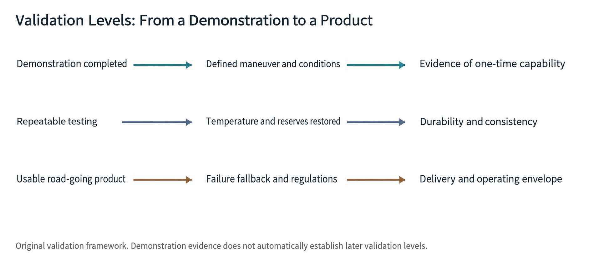
The most persuasive next step is a repeatable test protocol, rather than a still shorter single launch time. Acceleration tests should state whether rollout is deducted, how the surface is prepared, tire model and temperature, actual vehicle mass, battery state of charge, gas-cylinder pressure and environmental conditions. Each affects the result. Two figures become meaningfully comparable only when their conditions are transparent.
Repeated-performance testing should at least record battery, motor, inverter, fan and brake temperatures after each acceleration run, together with the cooling or gas-replenishment time between runs. Comparing total completion time, performance degradation and maintenance needs over a complete cycle is closer to actual use than comparing only the fastest run. Gas-equipped versions especially need a record of the recovery cost between the first and second run.
Chassis validation should cover speed bumps, road crowns, shoulders, standing water, gravel and damaged sealing edges, while recording pressure in each zone, ride height, tire slip and front-to-rear aerodynamic balance. The patent concepts of side-inlet backflow suppression, skirt zoning and rapid wing-angle adjustment also need validation with actual flow-field and dynamic data. Functional statements in a patent are not achieved-performance results. The aim is smooth, predictable degradation, not peak performance on every surface.
High-pressure-system validation should document pressure limits, temperature range, abnormal-leak detection, post-collision isolation, pressure-release direction and maintenance requirements. This does not require disclosure of trade secrets or details that could enable unsafe operations. Reviewable validation results need only establish how occupants, service personnel and bystanders are protected.
Finally, prototypes, production-intent prototypes, certification vehicles and delivered products must be distinguished. The same exterior can represent different levels of maturity, while software, materials, actuators and gas-storage arrangements may continue to change. The most accurate assessment of the 2026 launch stage recognizes the system-level innovation while retaining unsubstantiated performance under targets and pending validation, rather than presenting it prematurely as a production conclusion.
A practical validation checklist
| Validation area | Suggested published records | Question answered |
|---|---|---|
| Repeated acceleration | 10 runs under identical conditions; timing rules, state of charge, gas pressure, mass and temperature | Can the best run be repeated? How long does recovery take? |
| Sustained track use | 20 minutes of lap times and power; cooling and gas-refill stops | Heat-related performance fade and consumables cost |
| Wet and uneven surfaces | Pressure, ride height, slip and attitude changes | Are changes in sealing controllable? |
| Degraded operation | Fan, valve, sensor and power-supply failures | Is the reduction in performance predictable? |
| Tire capability | Compound, temperature, speed and load ranges | Can the additional downforce be sustained? |
| Gas replenishment | Refill locations and duration; inspection and service intervals | What happens in real use after reserves are depleted? |
| Product status | Certification scope, version equipment, delivery dates and warranty terms | Which functions can be purchased and used? |
These are suggested validation items and illustrative test durations, not procedures Tesla has committed to adopt. A technical report is useful when it identifies the most discriminating evidence to seek next, rather than issuing a final verdict on the product.
Conclusion: Public descriptions of the new Roadster combine tire traction, active suction and direct gas thrust. The engineering appeal is genuine, but the available information cannot establish that all display and demonstration vehicles share the same internal configuration. Independent repeated-performance data under consistent conditions are also missing. Patent disclosures reveal additional feasible structural approaches, but do not establish installation in the vehicle or completed production validation. Repeatable performance depends on gas replenishment, sealing and thermal management, not only on a sub-second peak; the most useful next evidence is repeatable data with stated conditions, rather than another isolated peak.
References and image sources
The links below provide traceability to public information. Product photographs remain copyrighted by their respective rights holders; an open license has not been confirmed. Permission should be checked separately before republication or commercial distribution. Original patent drawings retain their component numbers; local cropping only removes page margins and adjusts reading orientation. The 3D figures interpret the cited embodiments. Their colors, exploded spacing, hidden contours and apparent thicknesses have no manufacturing or measurement significance.
Timing clarification: Hagerty’s official description quotes a Rocket time of 0.55 seconds with rollout [9]. It cannot be directly compared with 0.59 seconds without consistent timing definitions. Also, 60 mph equals 96.56 km/h, not 100 km/h. Regional and left-hand-drive availability restrictions on the official site should be checked for the intended market.
[1] Tesla current UK Roadster product page — https://www.tesla.com/en_GB/roadster [2] Top Gear technical introduction to the actual car, 16 October 2026 — https://www.topgear.com/car-news/electric/tesla-roadster-has-finally-landed-thrusters-0-60mph-059s-and-flight [3] MotorTrend 2028 Roadster First Look, on-site interview — https://www.motortrend.com/news/first-look-2028-tesla-roadster-performance-thrust-rocket [4] NASA Rocket Thrust Equation — https://www1.grc.nasa.gov/beginners-guide-to-aeronautics/rocket-thrust-equation/ [5] NASA Specific Impulse — https://www1.grc.nasa.gov/beginners-guide-to-aeronautics/specific-impulse/ [6] McMurtry official account of upside-down driving — https://mcmurtry.com/upside-down-driving/ [7] Gordon Murray Automotive T.50 official technical description — https://www.gordonmurray.com/press/t50-global-reveal [8] Top Gear new-car video and public transcript; timestamps cited in the text — https://www.youtube.com/watch?v=JdkIOhFmbKI [9] Hagerty interview with Henry Catchpole and Lars Moravy; official video description — https://www.youtube.com/watch?v=22rvpUecLts [10] NASA COPV Damage Tolerance Life Demonstration Guidelines — https://www.nasa.gov/centers-and-facilities/nesc/copv-damage-tolerance-life-demonstration-guidelines/ [11] US12746987B1 Electric Fan Car, granted 29 September 2026 — https://patents.google.com/patent/US12746987B1/en. The original drawing reproduced in the report is FIG.1; the 3D interpretation is based on FIG.1, FIG.2 and FIG.3A. The side-inlet discussion corresponds to FIG.3B; alternative air paths must not be combined. [12] US12377920B1 Adaptive Vehicle Aerodynamics for Downforce, granted 5 August 2025 — https://patents.google.com/patent/US12377920B1/en. The original drawing and 3D interpretation use FIG.1; the alternative zone arrangements refer separately to FIG.2 and FIG.3, and the control architecture appears in FIG.4 and FIG.5. [13] US20260285418A1 active rear wing, published application, 24 September 2026 — https://image-ppubs.uspto.gov/dirsearch-public/print/downloadPdf/20260285418. The original publication has 29 pages; this report uses FIG.3A and FIG.3B on PDF page 5. FIG.4 and FIG.5 show alternative mechanisms, not the same assembly. [14] US9692277B2 Integrated electric motor assembly — https://patents.google.com/patent/US9692277B2/en. FIG.5, original PDF page 7; an earlier Tesla integrated single-motor assembly used as a technical reference. [15] US11962030B2 Integrated energy storage system — https://patents.google.com/patent/US11962030B2/en. FIG.5, original PDF page 7; a reference for an integrated energy-storage structure, with adoption by the new Roadster unconfirmed. [16] US9065103B2 Battery mounting and cooling system — https://patents.google.com/patent/US9065103B2/en; US20140193683A1 Battery Pack Base Plate Heat Exchanger — https://patents.google.com/patent/US20140193683A1/en. They illustrate thermal-management approaches from different generations, not direct drawings of the new car’s dual-sided cooling arrangement.
Patent evidence limits: A grant establishes that a patent was granted, while a published application establishes that the text was made public; neither automatically proves Roadster adoption, achieved performance or certification status. The wing section centers on the bilateral four-bar linkage in FIG.3 of US20260285418A1, analyzing deployment and angle adjustment separately; the fan section focuses on the inlet, diffuser duct and rear outlet of US12746987B1, with side-inlet backflow suppression belonging to another embodiment; and the skirt section primarily uses US12377920B1 to explain the movable front skirt and alternative zone arrangements, without combining all designs into one actual vehicle. Failure to locate a particular detailed drawing only defines the evidence available to this report; it does not prove that the drawing does not exist.
Image index
- Demonstration images A–F: Euronews on-site news video, 16 October 2026. The original footage includes the Tesla LIVE mark; frame times are measured from the start of the news edit: 00:19.80, 00:30.20, 00:36.50, 00:37.80, 00:39.20 and 00:39.60.
- Figure 1 — https://digitalassets.tesla.com/tesla-contents/image/upload/f_auto,q_auto/Roadster-08-End-Desktop.jpg
- Figure 3 — https://www.topgear.com/sites/default/files/2026/10/_B8A5491.jpg
- Figure 6 — https://www.topgear.com/sites/default/files/2026/10/_B8A5856s.jpg
- Figure 7 — https://www.topgear.com/sites/default/files/2026/10/_B8A5667.jpg
- Figure 12 — https://www.topgear.com/sites/default/files/2026/10/_B8A5741.jpg
- Figure 15 — https://www.topgear.com/sites/default/files/2026/10/_B8A5511.jpg
- Figure 17 — https://hips.hearstapps.com/hmg-prod/images/5e94ff62-4ac5-462e-b395-693b11611c47.jpg
- Figure 18 — https://www.topgear.com/sites/default/files/2026/10/_B8A5655.jpg
- Figure 19 — https://www.topgear.com/sites/default/files/2026/10/_B8A5695.jpg
- Figure 20 — https://digitalassets.tesla.com/tesla-contents/image/upload/f_auto,q_auto/Roadster-03-Carousel-Slide-5-Desktop.jpg
- Figures 2, 16 and 21 are original explanatory schematics; Figures 4, 5, 8, 9, 10, 11, 13 and 14 are based on the corresponding patent embodiments, and the 3D interpretations carry no measurement significance.
Calculation check and model limits
Calculation check: 60 mph = 26.8224 m/s; 26.8224 ÷ 0.59 = 45.4617 m/s². Dividing by the standard gravitational acceleration of 9.80665 m/s² gives 4.64g, and this standard-gravity value is used consistently throughout. At an assumed mass of 2000 kg, the change in momentum is approximately 53.64 kN·s, translational kinetic energy is about 719.4 kJ, and the constant-acceleration distance is about 7.91 m. These calculations omit wheel rotational inertia, drag and short-duration mass changes; they are not a whole-vehicle certification model.
Model limits: The effective area of 3 m², pressure difference of 10 kPa, flow of 5 m³/s, overall efficiency of 60%, friction coefficient of 1.5, effective exhaust velocity of 500–700 m/s and the 100 kWh charging example are illustrative calculation inputs. They are not Tesla specifications and are not used to infer actual vessel, nozzle or floor dimensions. The packaging discussion describes qualitative constraints; this report does not scale patent drawings to estimate the new car’s dimensions.