
OCP 2026 Panorama
The system boundaries and industry opportunities of AI infrastructure
Information cutoff: October 15, 2026, 10:06 UTC 18:06 Beijing and Singapore time · 03:06 PDT in San Jose
The most important change at OCP 2026 is that the unit of design, delivery, and operation in AI infrastructure keeps getting larger. Chip performance sets local ceilings; the rack and multi-rack communication domains determine how compute cooperates; power, cooling, and failure recovery determine whether that compute can continuously become a sellable service. The value of open standards therefore extends beyond servers — but the degree of openness, interoperability, and commercial maturity differs widely from layer to layer. Buying a rack that conforms to open interfaces does not mean its accelerators, interconnects, and software can already be freely swapped.
For server, cloud, and storage product teams, the shared direction this summit points to is this: move product promises from peak specifications to verifiable system outcomes. A product should be able to answer for real workload throughput, tail latency, sustained power and cooling capacity, effective capacity after failures, and time to deployment. For token factories whose core business is model serving, the more appropriate target is effective output under quality and latency constraints, not raw tokens per second.
This report takes OCP 2026 to mean the OCP Global Summit held October 12–15 in San Jose, together with official announcements made immediately before it. As of the cutoff, the final day's daytime agenda had not yet taken place, so this is a panorama in progress; announced agendas are not treated as releases or deployments that have already happened. Sources are primarily OCP, vendor announcements, formal technical documents, and code repositories; vendor performance figures keep their tested-or-projected status, and the engineering judgments and action suggestions here are not measured gains. [1]
01 The System Boundary Expands, and Openness Diverges
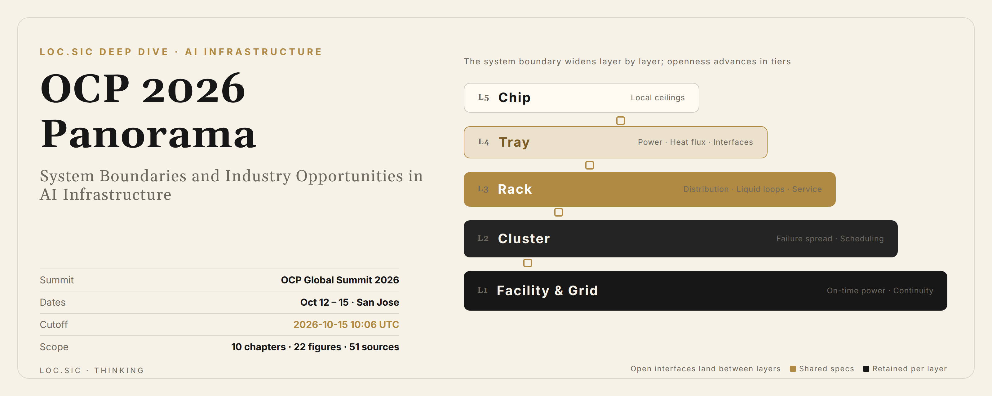
To absorb this year's technical density, first separate the design object into mutually constraining layers. Models and the business determine compute, memory capacity, and communication shape; accelerators and CPUs determine the tray's power, heat flux, and interfaces; the rack determines power distribution, liquid loops, cabling, and serviceability; the cluster determines failure propagation and resource scheduling; the facility and grid determine whether everything can come online on schedule, stay powered, and keep growing. A change at any one layer can force adjacent layers to re-validate. That is the root reason rack-scale integration looks increasingly attractive — and it explains why a single chip's advantage does not convert directly into the economics of a whole service.
OCP had already laid out the chip-to-grid data center vision in October 2025. The 2026 increment is mainly converting that vision into more interfaces, reference designs, and cross-domain collaboration; it should not be repackaged as a first-time proposal this year. OCP also states plainly that the 800 VDC busbar and layout still need work, and that common open elements for optical interconnect are not yet fully defined. The direction is fairly clear; the implementation still has gaps. [2]
"Open" covers at least four distinct capabilities. Design documents being available helps suppliers understand the system; interfaces having a common specification helps different parts connect; multi-vendor validation existing helps customers reduce replacement risk; the software and operations chain being portable helps customers actually switch suppliers. The first three can improve gradually; the fourth is usually hardest. If drivers, communication libraries, compilers, and failure diagnostics remain deeply bound to one platform, the main gain from opening mechanical and electro-thermal design is a larger manufacturing and integration ecosystem — not the immediate removal of platform dependence.
In engineering terms, openness also redistributes responsibility. A vertically integrated platform has one supplier accountable for the system outcome; an open composition needs someone to own cross-component validation. Customers gain more options but cannot skip compatibility matrices, firmware co-debugging, off-nominal testing, and spares management. An open scheme with real commercial value should state clearly who is responsible for link errors, leaks, power excursions, and cluster recovery — and which software and hardware versions that responsibility covers.
The summit is therefore better read as a collection of engineering progress at different maturity levels. A formal specification supplies a common language; a reference design provides a reusable starting point; a booth demo proves operation under specific conditions; a planned launch signals supply intent; only running at scale provides evidence of sustained reliability. A product roadmap may draw on all of these signals; a procurement commitment should rest mainly on deliverable configurations and re-verifiable data. The chapters that follow discuss each technical direction along this line.
02 Compute Platforms and CPUs Redivide the Work
Rack-scale platform competition now spans accelerators and CPUs at once. At this summit NVIDIA published parts of the Vera Rubin rack and tray design; MGX 1.2 supports up to 250 kW and adds blind-mate liquid cooling interfaces. What is open here is a selected system design. 250 kW is an architecture support value — not the practical power of every deployment, and certainly not evidence that the GPU and software platform is open-sourced. [3]
AMD Helios is the example of multi-year evolution. It was shown in 2025; this year's emphasis is production ramp, initial customer installs, and workload validation. AMD showed Verano on the same stage, but its availability still points to 2027. The platform is moving from design toward delivery — not yet proof that all customers are in stable mass production. [4]
AMD's new blueprint, Helion, highlights a different class of demand: agent execution does not only consume model-inference resources; it also needs sandboxes, code execution, orchestration, and general-purpose services. The official material describes CPU-only and CPU/GPU hybrid racks and plans to contribute the specification; partner configurations remain in development, with availability targeted for November 2026. Numbers like the 32,768-core ceiling are configuration maxima and cannot be summed with every other maximum in the hybrid rack. [5]
The product significance is not finding one fixed CPU-to-GPU ratio. Retrieval, browser operation, code execution, and long waits on external tools produce completely different resource curves. Many short-lived sandboxes may first hit startup latency and isolation overhead; data-intensive tools may hit CPU memory bandwidth; a service that only routes simple tool calls may not need a high-density CPU rack at all. Teams should start from execution traces of each task class — CPU active time, memory residency, overlap between I/O and model calls — and then decide between separate scaling and hybrid deployment.
Separating a pure CPU pool from the inference cluster lets each scale to its own demand and insulates agent-execution resources from model generational changes. Hybrid racks are easier for mid-size enterprises to buy and operate, but more prone to one side saturating while the other idles as business mix shifts. A server vendor that delivers validated combination ranges, independent maintenance units, and consistent management interfaces creates more value than one that simply offers more SKUs.
Arm's agentic benchmarks released this summit belong in the same frame. The published Signal65 validation covers server measurements and rack-level modeling — not a universal whole-rack-versus-whole-rack conclusion for all workloads. Different charts also use different AMD baselines. CPU selection should replay your own sandbox, retrieval, and orchestration workloads; an average multiplier is not a general architectural advantage. [6]
One more branch worth tracking is the large-capacity, lower-power inference card. Intel's summit material describes the LPDDR5X-based GPU D-series, now in customer sampling; the "up to 480 GB" covers ODM-configurable builds, while Intel's own-brand card is 160 GB. Capacity buys room for model state, but long-context and high-concurrency throughput still depend on bandwidth, data layout, and software execution efficiency — it does not equate to HBM-platform throughput. [7]
03 Supernodes Must Be Compared by Communication and Failure Boundaries
Microsoft Maia 300 shows the route of pushing inference systems toward ever-larger communication domains. The official configuration is 96 accelerators at 167 kW per rack, with production deployment planned from 2027. Its efficiency gains over GPU systems are projections; the multiple over Maia 200 is whole-rack token throughput — neither a universal same-power comparison nor a per-chip gain. The Maia 200 in production today and the future Maia 300 should stay separated. [8]
The architecture documents further describe a common communication-semantic scope of up to 128 racks and 12,288 accelerators, electrical within the rack and optical across racks. Different paths have different hop counts and latencies; the cross-rack bandwidth figures carry concurrency conditions and cannot be read as all devices passing traffic unblocked simultaneously. What merits analysis is how the system hands a larger communication range to software. [9]
A large communication domain gives model placement more combinations and may make idle capacity easier to exploit. But common communication semantics are not uniform physical latency. Tensor parallelism, expert parallelism, pipeline parallelism, and prefill/decode separation differ in communication sensitivity. The scheduler needs to know the difference between local, same-rack, and cross-rack paths — keeping frequent synchronization inside tighter scopes and putting capacity expansion where extra path delay is tolerable. Otherwise a nominally larger resource pool can turn into more synchronization wait.
In cross-vendor comparison, node counts mislead most easily. A 72-accelerator rack, a 96-accelerator rack, and a communication domain addressing tens of thousands of devices are not the same layer. Compare, item by item: the task scope that can jointly execute, actual collective or all-to-all efficiency, tail latency under congestion, and the smallest unit affected by maintenance. Peak link rates explain only part of this.
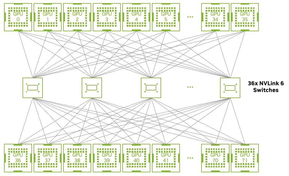
Integration density also changes the arithmetic of reliability. At larger scale, per-component failure observations arrive more often; what matters is whether failures stay locally contained and whether applications can keep serving in degraded mode. A hot-pluggable tray does not mean tasks recover automatically; spare accelerators do not remove the need to rebuild state. Acceptance should cover the full sequence of link degradation, node withdrawal, restart, and capacity backfill — with recovery time, lost work, and remaining serviceability written into the test.
For cloud products, then, supernodes enable finer service tiers. Tightly coupled jobs buy low-latency domains; loosely coupled inference and independent agent tasks use more elastic pools — each tier with matching pricing and availability commitments. The resource boundary hardware enlarges becomes customer-visible performance only through observable topology and enforceable scheduling policy.
04 Network Standards Have Not Converged on One Protocol
Networking needs to distinguish scale-up, scale-out, and cross-facility connection. The first serves tightly coupled accelerator traffic; the second carries training and serving traffic for larger clusters; across buildings or campuses, propagation delay and failure boundaries become explicit. All can share the Ethernet component and operations ecosystem — that does not mean transport semantics, congestion control, and error recovery have unified.
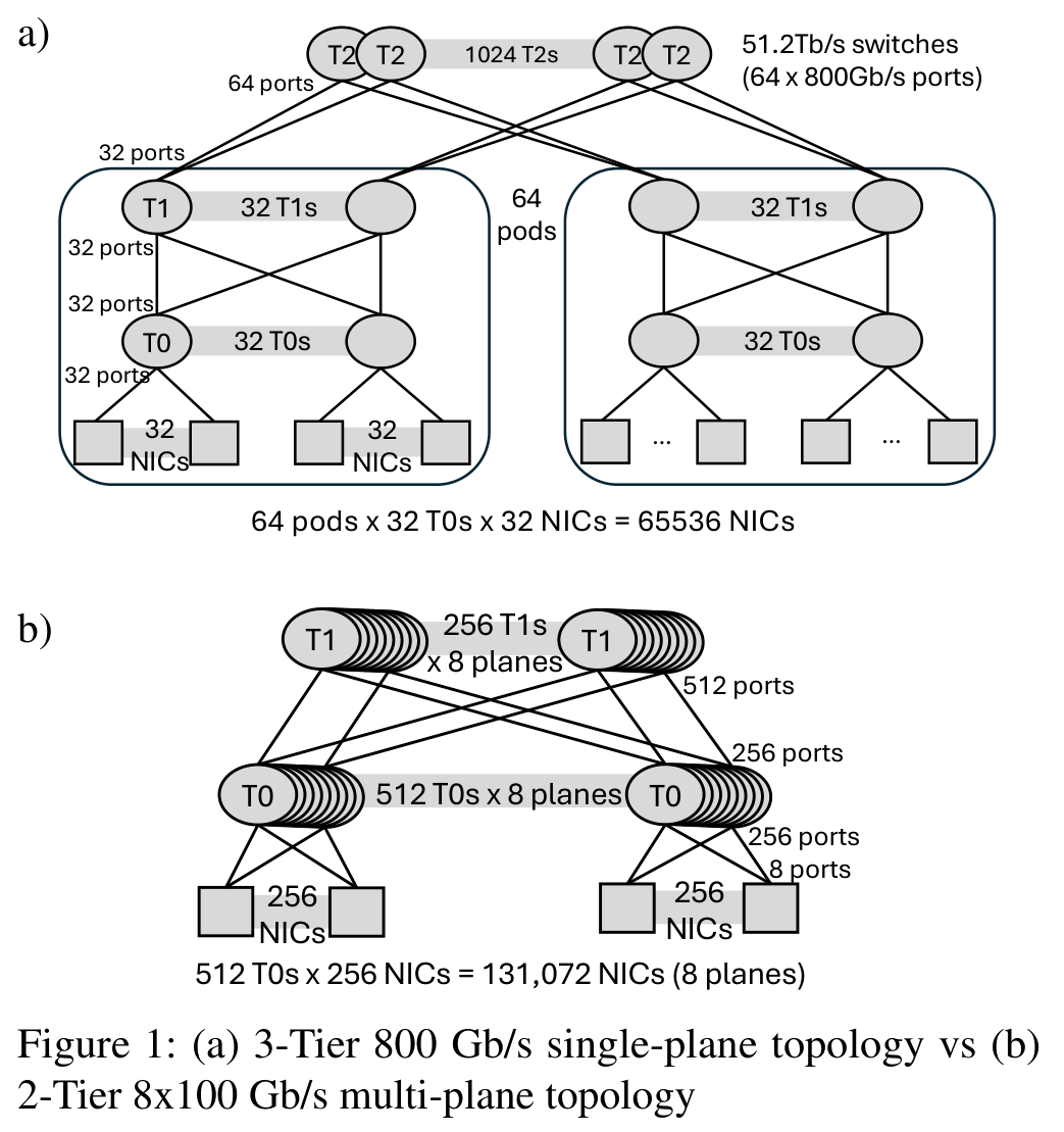
Multipath Reliable Connections (MRC) is this year's important production evidence — and it did not first appear at this summit. OpenAI published the scheme and its large GB200 cluster deployment in May, improving scaling via multiple planes, packet spraying, and endpoint recovery. The progress here is turning path diversity into a system-usable capability; its congestion and loss-handling assumptions differ from PFC-based lossless Ethernet. [10]
Meta's summit material shows a different, incremental route: the currently shipping Tahan uses existing RoCE mechanisms, while the larger future scale-up design plans to adopt ESUN. Meta also proposed an open switch-platform abstraction to reduce fragmentation across sensors, firmware, and power management. One company can run multiple network generations and semantics simultaneously — "fully moved to the new protocol" is not an accurate summary. [11]
The ESUN 1.0 specification was published earlier this year; its core is the operator's requirements on the fabric, with 1.1 in progress. UALink 2.0 also shipped in April, covering compute, management, and layered evolution. Public specifications provide a common development base; they do not substitute for endpoint and switch-silicon supply, communication-library adaptation, and cross-vendor interoperability acceptance. [12][13]
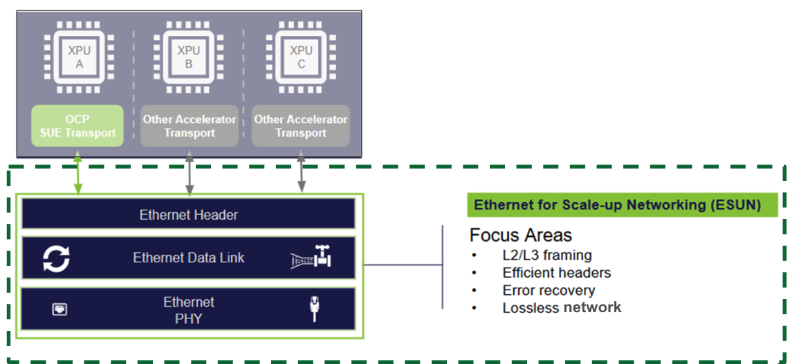
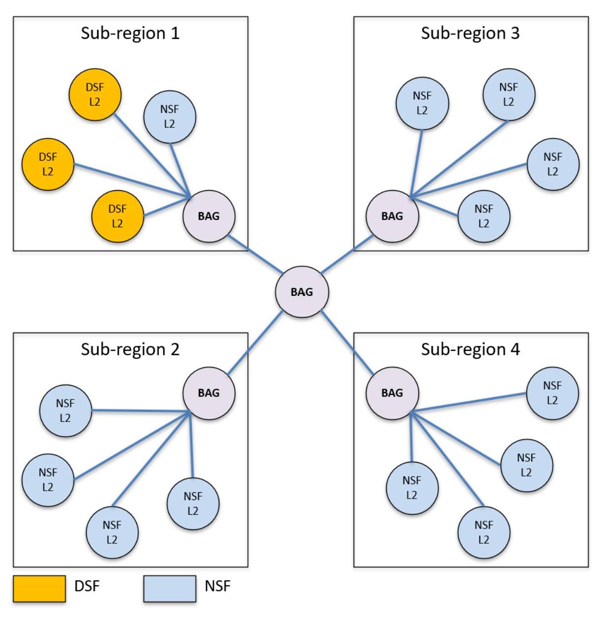
The engineering appeal of multi-plane networks is using more independent paths to reduce tiers and turn some failures into tolerable bandwidth loss. The cost is that reorder, path selection, congestion feedback, and telemetry lean harder on endpoint–network cooperation. Switches having the same speed — or all running SONiC and SAI — does not prove consistent upgrade, QoS, or recovery behavior. Acceptance should cover loss, microbursts, single-path failure, and mixed load, not just congestion-free throughput.
Network product teams should decompose "supports protocol X" into a clear capability table: endpoint versions, switch configuration, communication libraries, tenant isolation, congestion algorithms, and observable metrics. Cloud teams should co-design network topology with model scheduling. Before tasks span farther regions, assess communication share and tail-latency budget; geographically distributed capacity has value for disaster resilience and power, but it is not automatically a supernode equivalent to a single rack.
05 Optical Interconnect Enters the Systems-Engineering Stage
Co-packaged optics (CPO) moves the optical engine next to the switch or compute die, trying to shorten high-speed electrical links; pluggable modules keep the advantages of field maintenance and independent replacement. OCP 2026 showed investment on both routes — a more realistic picture than "one optical form is about to win everything." The USFP announced by NVIDIA and Cisco targets higher bandwidth density; the open specification and multi-source community projects remain plans, not a completed supply chain. [14]
CPO maturity is uneven. Celestica announced the DS6005 system; Lightmatter's switch is a production-validation platform, while its compute trays are proof-of-concept; Wiwynn, Ayar Labs, and GUC demonstrated a functional validation of an integrated optical compute system. These are meaningful systems progress — not proof that every approach has volume delivery and years of field record. [15][16][17]
In engineering terms, shortening the electrical link may cut related component power, but shifts some complexity into packaging, fiber coupling, cleanliness, thermal drift, and the maintenance boundary. External, replaceable lasers improve serviceability for some failures, but an optical-engine or package failure may still require swapping a larger assembly. System comparisons must use one power boundary — counting lasers, controllers, cooling, and redundancy — rather than treating local savings as whole-system savings.
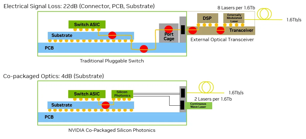
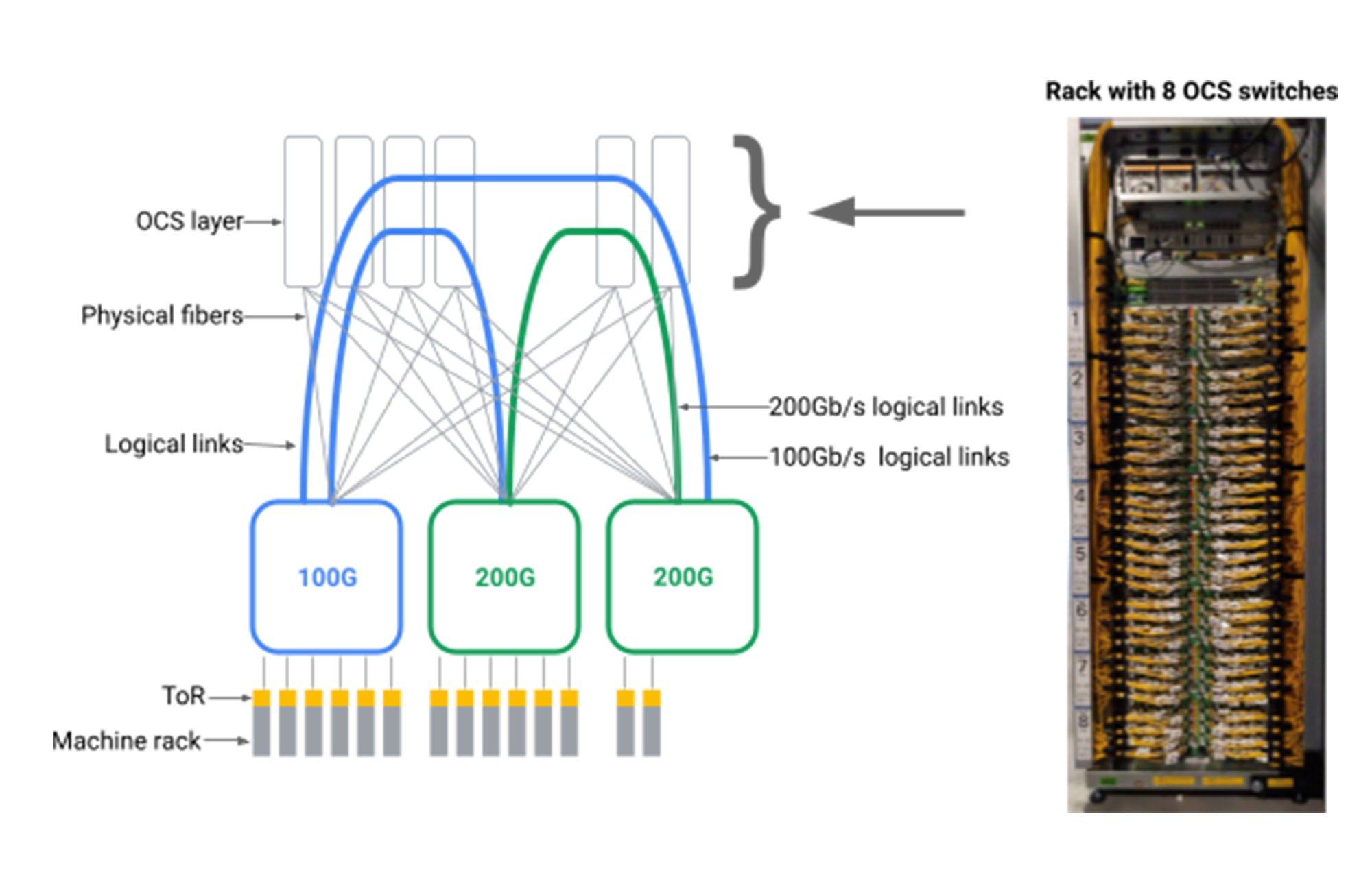
Optical circuit switching (OCS) deserves its own discussion. It changes the optical path topology; CPO changes where electro-optical conversion happens; the two can combine but solve different problems. OCP's OCS work covers interfaces, control, telemetry, and interoperability. Its benefits depend on predictable traffic and a matching scheduler; reconfiguration time and transient effects must enter task evaluation. [18]
Near-term product decisions should keep a maintainable optical route while building a small CPO validation environment. Procurement questions should extend beyond port speed to optical-port failure rates, blast radius of laser failures, field cleaning, blind-mate lifetime, and spares cost. Higher optical integration becomes a bankable advantage only when system-level savings and business gains clearly exceed the added maintenance complexity.
06 HVDC Brings Power Constraints into Compute Design
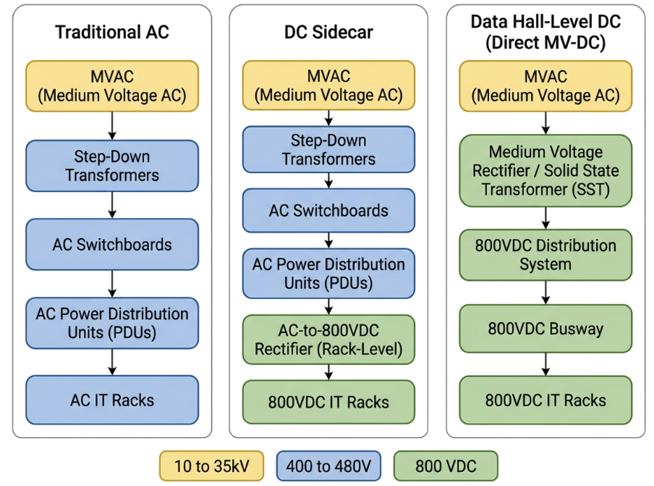
The mechanism of raising voltage can be shown with a simplified calculation. In steady state, ignoring conversion losses, redundancy, and distribution topology, delivering 1 MW at 48 V implies about 20.8 kA; at 800 V, about 1.25 kA. The example explains why high-power racks push toward high-voltage distribution; it does not mean copper loss or system energy drops by the same multiple, and it is not a design recommendation for specific equipment. Conductor length and cross-section, conversion stages, protection strategy, and safety requirements all change the answer.
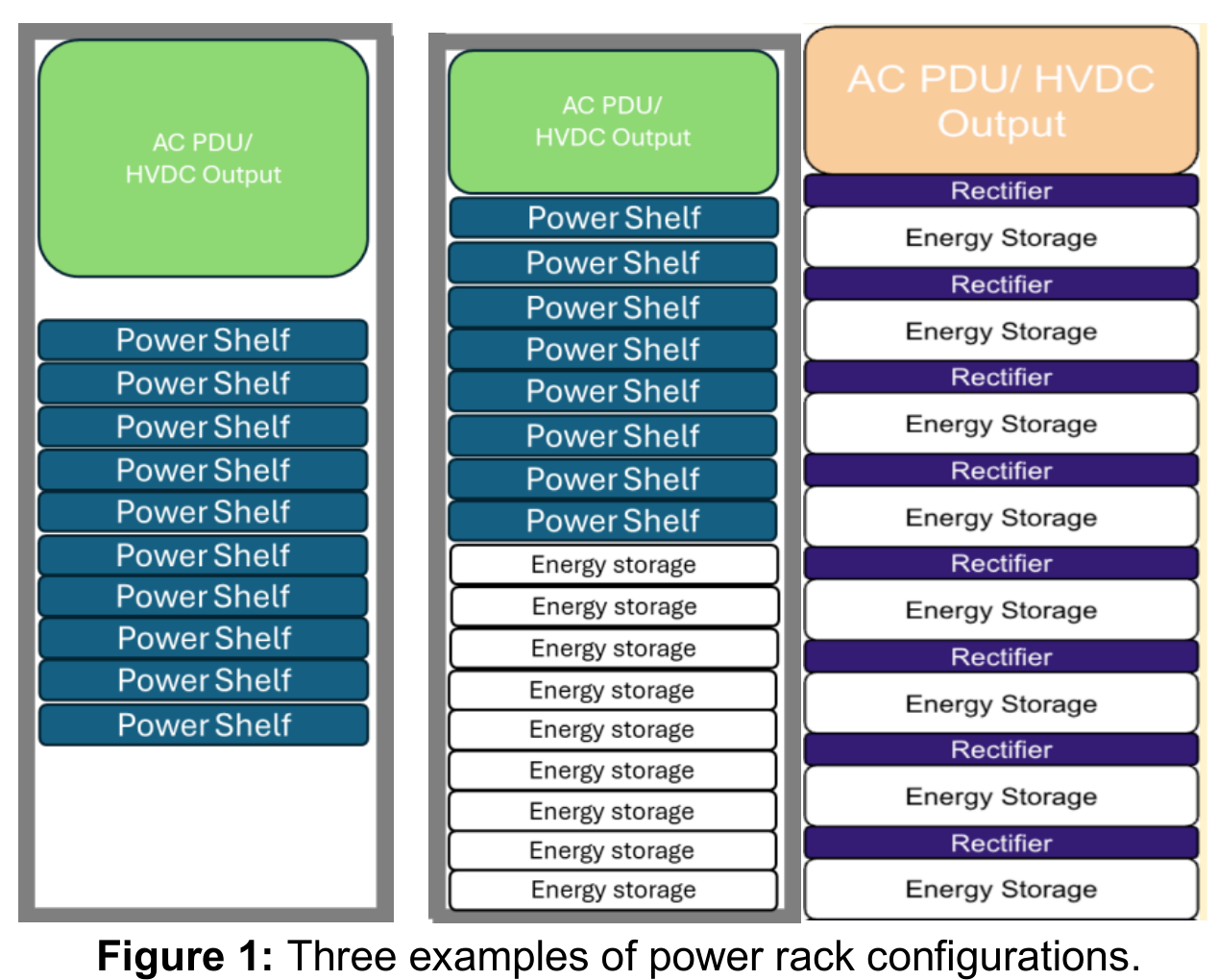
The Diablo sidecar route separates power conversion from the IT rack, leaving room to scale power and compute independently. The verified OCP v0.7 document covers ±400 V or 800 V plus energy-storage options, but some connector content still has open items. The sidecar is thus a reusable architectural direction, not proof that all vendor interfaces have completed cross-validation. [19]
HVDC also does not require converting an entire building at once. NVIDIA described the staged path in August: from power cabinets in existing AC rooms, to in-row power, to native-DC facilities. These are multi-year routes and targets; they cannot all be booked as capabilities delivered at this summit. [20] Sidecars help phase the transition, at the cost of floor space and added protection-coordination requirements; row-level centralization may improve reuse but also widens the blast radius of some failures.
OCP Open Data Center v0.7 targets cross-vendor boundaries for future facilities and keeps air and liquid cooling combinable. Its power density and cluster scale are design targets, not 2026 deployment statistics. [21] For product teams, the facility interface's value is agreeing early on power, liquid, mechanical, and management conditions — reducing the rework of discovering after server completion that the building cannot take it.
The relation between grid disturbances and compute recovery is easier to overlook. OCP's disturbance interface specification requires, under qualified voltage conditions, restoring to 90% of pre-fault compute load within two seconds of normal voltage recovery; that scope is not a recovery guarantee for arbitrary building failures, and cooling load needs separate handling. [22] If the electrical system recovers before thermal capability, immediately rebounding compute can itself trip new protections.
Power control, cooling control, and task scheduling should therefore share state. How much load to restore after a fault depends on available power paths, flow rates, temperatures, and storage headroom; whether short-duration power caps cause task retries also needs application cooperation. A token factory should not optimize only rated-MW peak output — it must verify deliverable capacity under load steps, curtailment, and maintenance states. Storage, solid-state transformers, and on-site generation add options, but a show-floor demo cannot answer long-term cost and reliability.
07 Liquid-Cooling Procurement Moves to Interfaces and Lifecycle Validation
Liquid cooling has entered the procurement language of whole systems. How much heat a cold plate removes holds only at specified fluid, temperature, flow, and pressure differential. A CDU's rated MW, a rack's rated power, and a chip's TDP have no automatic one-to-one mapping. Any short board — connectors, filtration, degassing, water quality, pump redundancy, or facility-side heat exchange — can change the sustainably deliverable power.
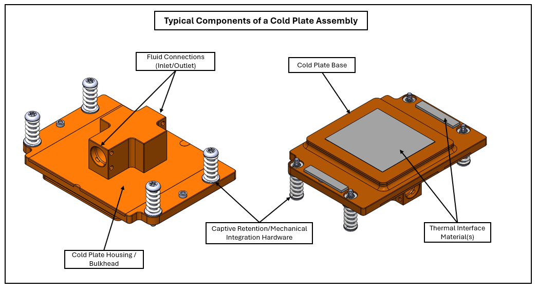
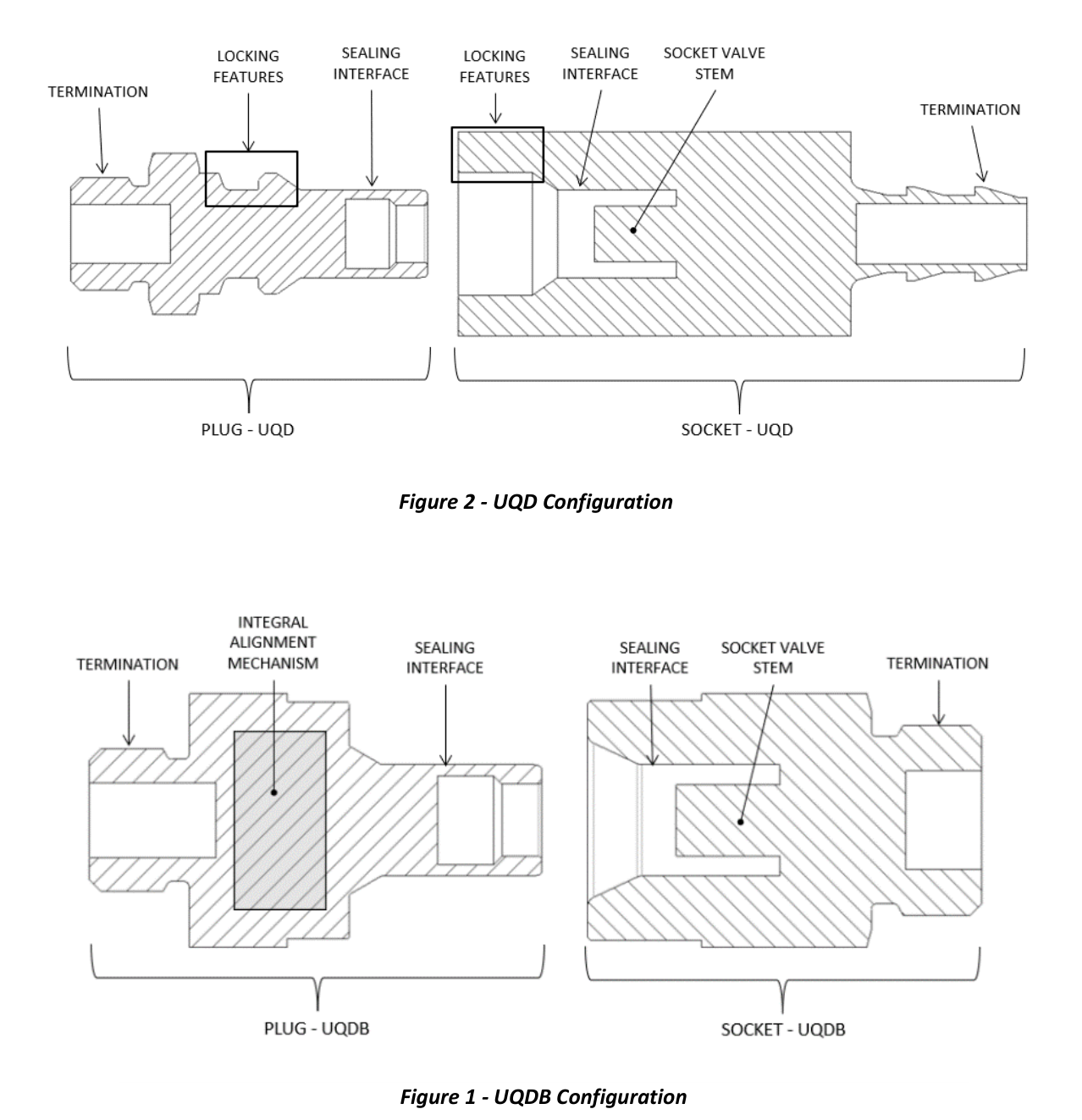
Specification progress from just before and during the summit deserves attention. UQD v2.0 merges manual and blind-mate requirements and includes supplier cross-validation; compatibility still needs deployment-specific assessment. The single-phase direct cold-plate test specification covers thermal resistance, pressure drop, leak rate, burst pressure, corrosion, and mechanical cycling. This work moves procurement from "maximum heat dissipation watts" to repeatable engineering acceptance. [23][24]
Standards cannot remove all mixed-vendor risk. Seal materials, dimensional tolerance, valve travel, and fluid conditions all affect real behavior. Even two products each claiming conformance need combined-state and post-aging validation by the customer. The maintenance boundary of the liquid loop must also be explicit: which valves close when a tray is swapped, how flow redistributes, whether a leak detection trips the whole rack, and who owns recovery.
Demo units should be assessed by their stage. Delta's release gives the Deschutes CDU's specific operating point and plans volume production in Q1 2027; Rittal and Bosch high-voltage sidecars are still development prototypes. Both help read the industry direction; neither can be written up as completed scale-run validation. [25][26] When comparing equipment, require the same supply/return temperatures, approach differential, redundancy state, and pump-power basis — otherwise rated capacity figures are not comparable.
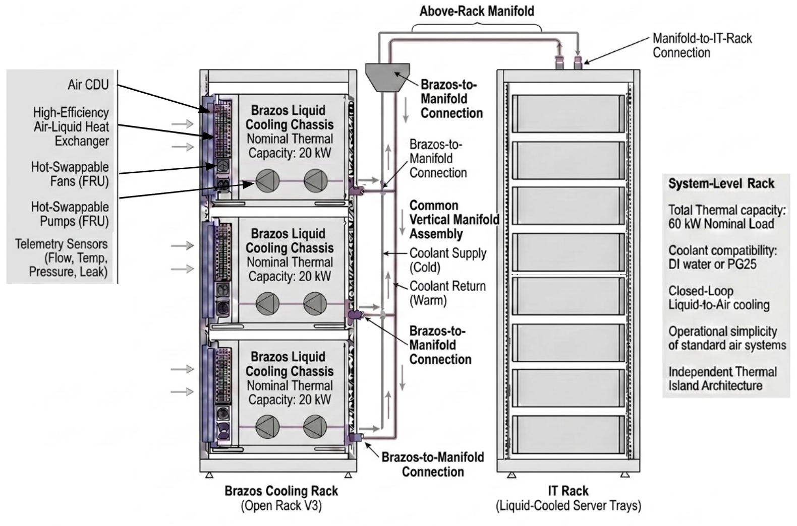
Route choice also has to reckon with the installed base. Google's Brazos, published earlier this year, is a liquid-to-air scheme for air-cooled rooms with sufficient power and air handling. Deploying liquid-cooled IT does not necessarily force a building-wide water retrofit — but a lower-power retrofit cannot be extrapolated to MW-class racks. [27]
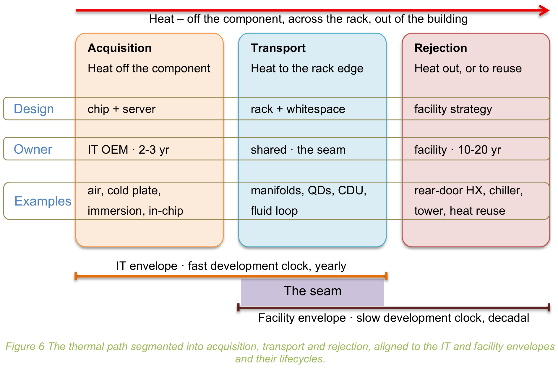
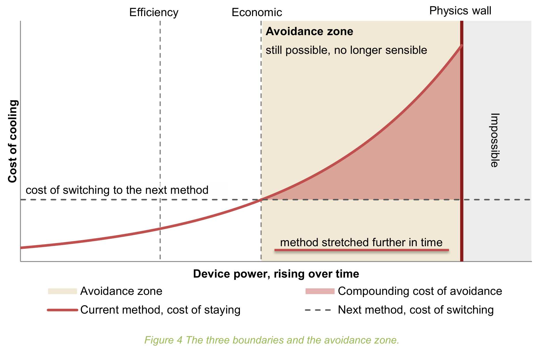
The more valuable engineering capability connects factory test, post-transit inspection, and on-site commissioning. Teams should validate partial load, single pump or power failure, redundant maintenance, real AI power transients, and thermal cycling. A cooling choice also trades power, water, footprint, and maintenance cost — not a single PUE number. OCP's new Thermal Boundaries white paper offers exactly this multi-constraint analysis frame, not a performance certification for any route. [28]
08 Memory and Storage Now Serve the Inference Working Set Together
An important shift in inference infrastructure: the working set no longer splits into "memory holds the model, storage holds files." Weights, KV cache, retrieved objects, session state, and agent-execution data have different lifetimes and reuse patterns. Hot data needs low latency or high bandwidth; the capacity tier needs lower unit cost; cold data needs reliable retention. The design problem is keeping the cost of moving data between tiers below the compute and waiting it saves.
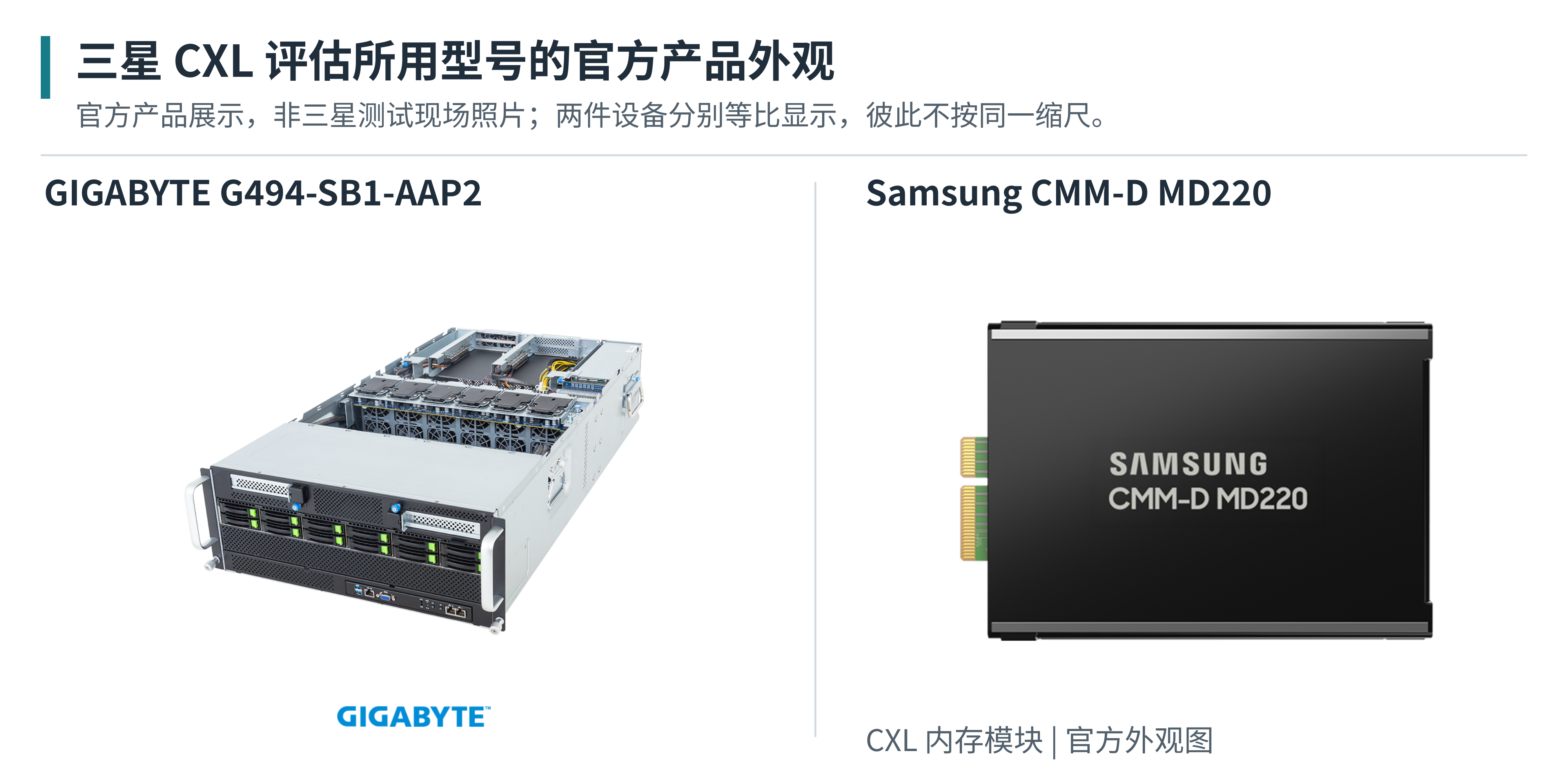
At this summit Samsung showed CXL dynamic memory pooling and a KV-cache scheme combining Flexible Data Placement (FDP), larger NVMe max transfer size (MDTS), and LMCache. The demonstration results depend on the specified workload and do not generalize into fixed gains for all models. The common point worth noting: hardware capacity is being designed together with runtime allocation, reclamation, and I/O policy. [29]
High-density SSDs add options for colder working sets. Samsung's BM1773 tech page lists up to 245.76 TB capacity with its endurance basis; Kioxia's LD4 shown at the summit is a limited-customer evaluation sample, with current sample capacity distinct from future expansion targets. Capacity growth alone is neither proportional endurance improvement nor proof the target product is in volume production. [30][31]
High-bandwidth flash (HBF) is the exploration of a read-optimized NAND tier closer to the xPU. The public v0.7 architecture document predates the summit; it differs from HBM in coherence, access profile, and purpose, and is not a mature drop-in equivalent. [32] For product planning, track HBF's interfaces, packaging, and runtime conditions first — do not pre-book realizable cost advantages from target bandwidth and capacity alone.
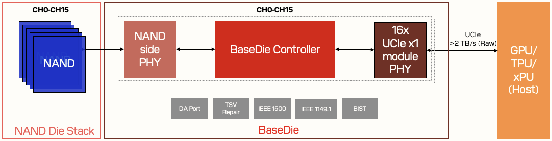
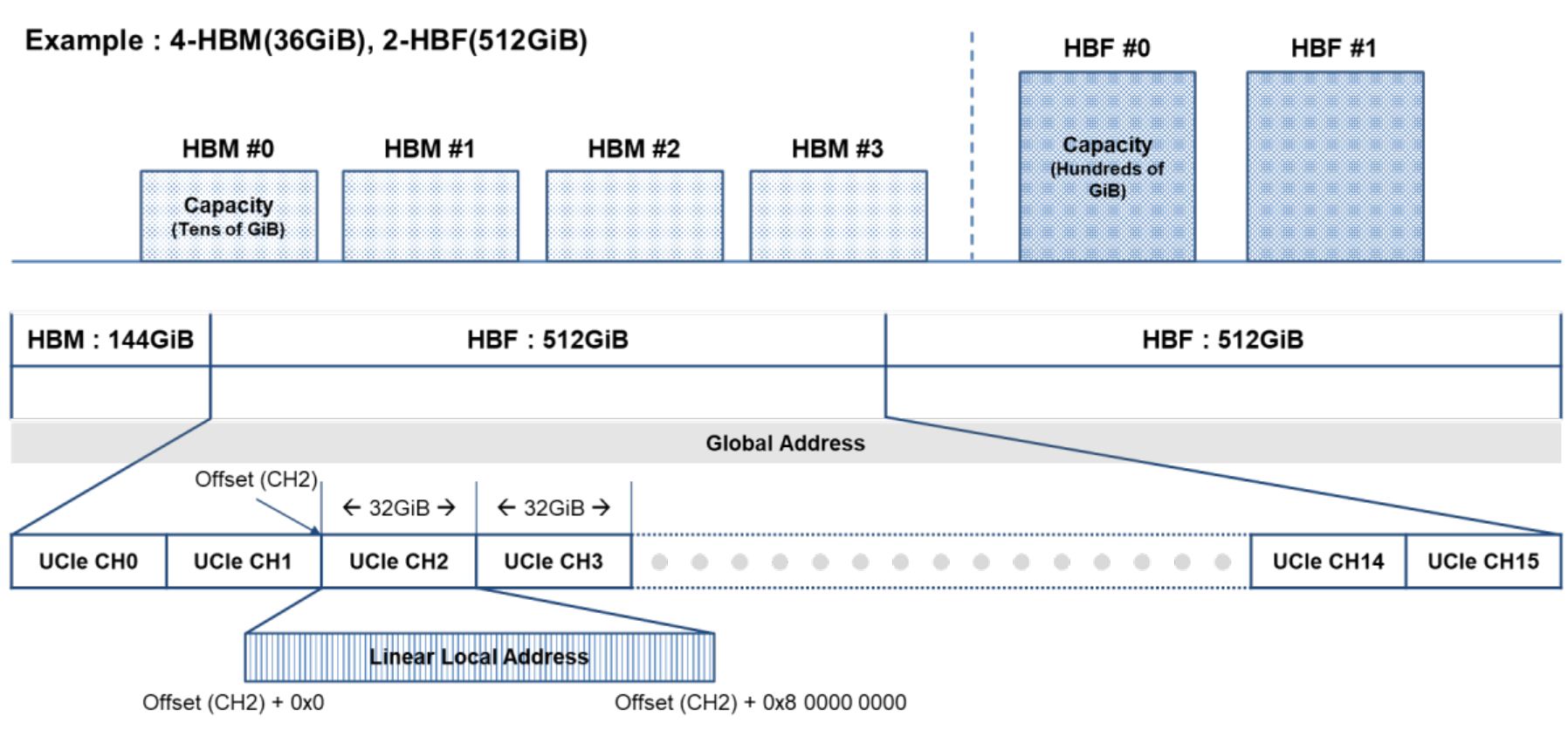
In engineering terms, KV tiering gains depend on reuse rate and the value of avoided recomputation, net of transfer, queuing, management, and invalidation-recovery overhead. Long contexts, multi-turn sessions, and multi-tenant agents may offer more reuse; short sessions may not justify migration. Cache hit rate alone cannot judge the gain: hitting one very cold but very large object can still hurt other requests through transfer occupancy. Observe time-to-first-token (TTFT), time-per-output-token (TPOT), and goodput at target SLOs under one model, precision, and request mix.
CXL pooling equally needs software boundaries. Scalable memory does not automatically mean every GPU accesses it at equal cost, nor that different tenants can share KV directly. NUMA, topology, ownership, encryption, reclamation, and migration policy must be defined together. If hardware exposes capacity while the runtime cannot place data correctly, pooling turns local capacity shortage into cross-link waiting.
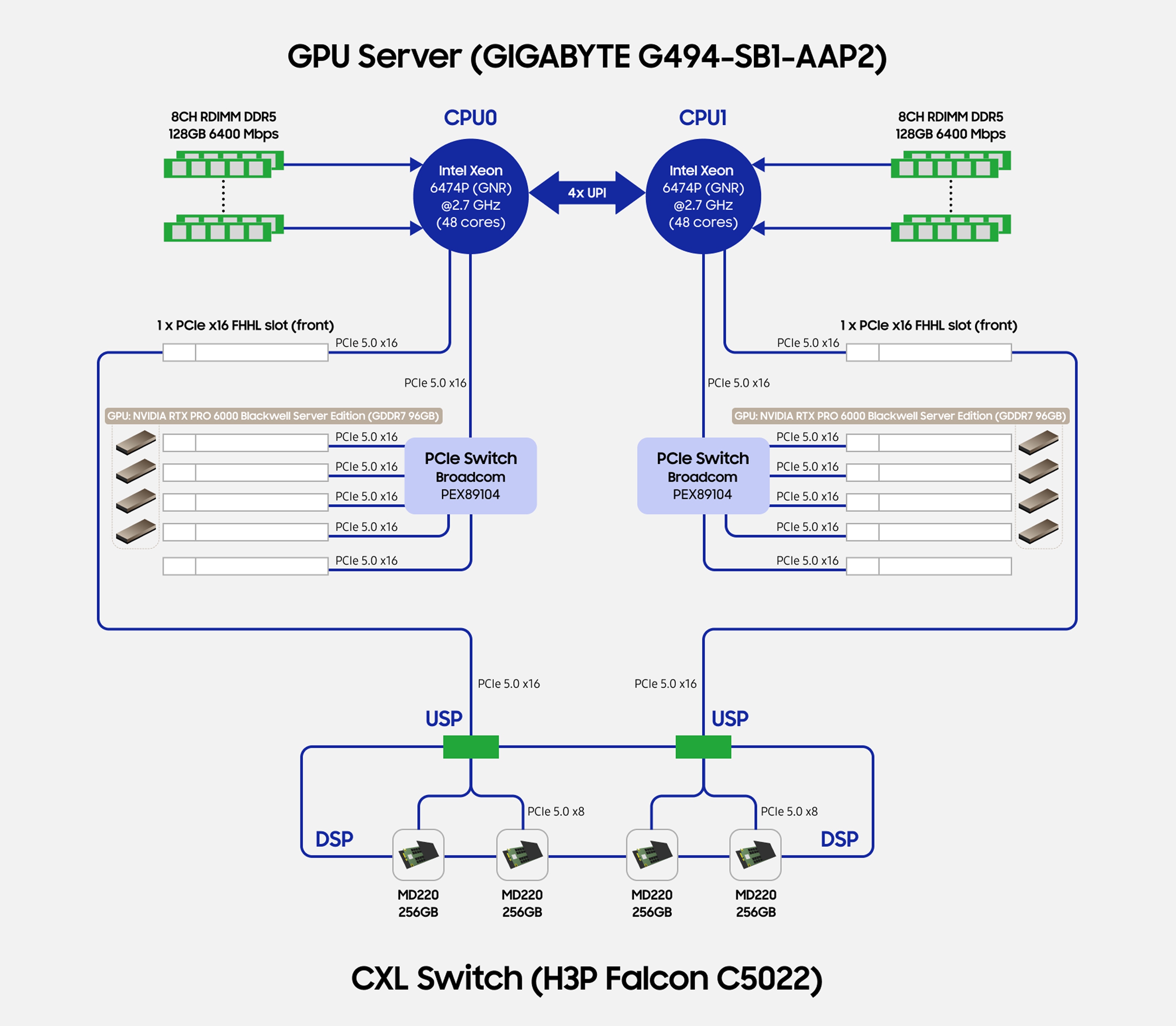
The server opportunity is orchestrating PCIe/CXL lanes, DRAM capacity, expansion slots, and power and cooling so GPU, NIC, and storage do not crowd each other's I/O. The storage opportunity extends to low CPU overhead, write-amplification control, QoS, cache lifecycle, and recovery. Cloud services should map these into billable capacity and service tiers — not just another "bigger memory" instance type.
09 Management and Security Extend to Racks and Clusters
Once a failure's impact crosses a single machine, management software needs the full dependency graph. A tray going dark could be its own firmware, power, liquid loop, network, or an upstream facility; if each system only raises its own alarms, recovery still depends on humans stitching the story. The real value of open management interfaces is letting these states be read, correlated, and handled consistently — not just putting more sensors on a dashboard.
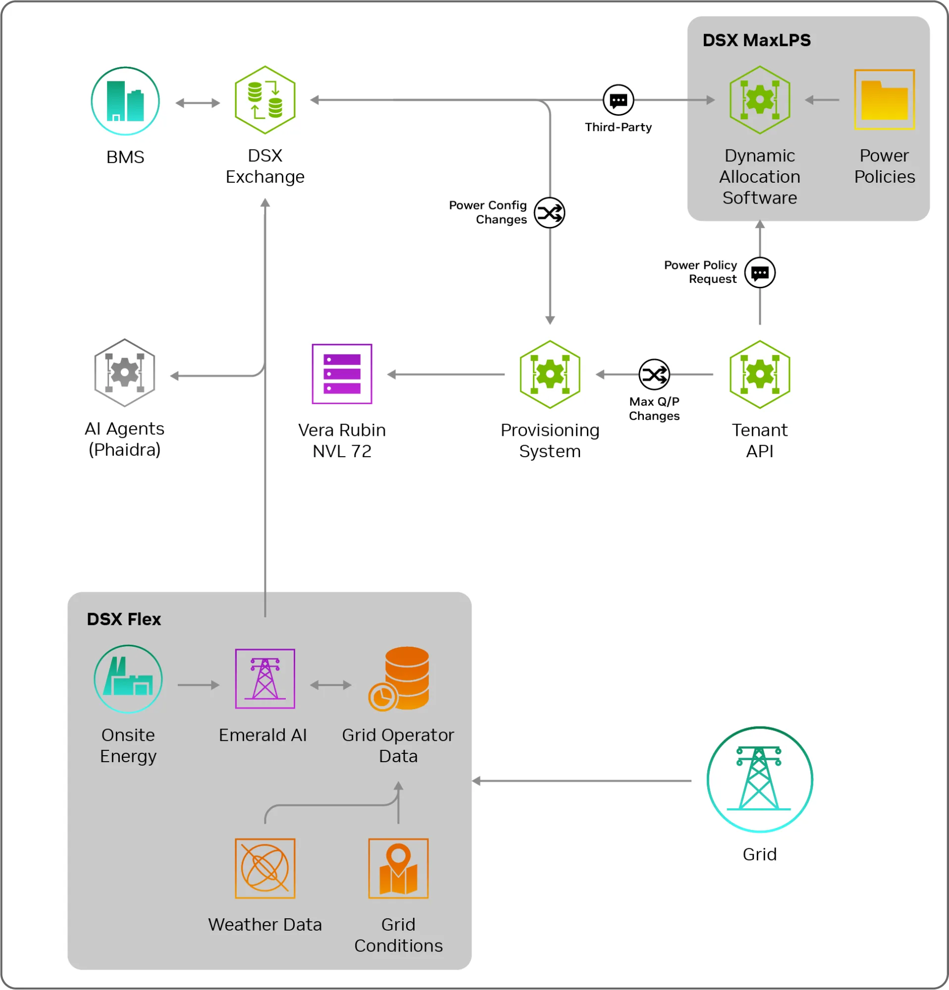
NVIDIA's open-sourced Rack Management Service brings rack power, inventory, firmware, and switch configuration into a service interface — but its reference object is NVIDIA's own infrastructure and it should not be assumed as every vendor's universal implementation. Its Cluster Readiness Engine uses communication and training tests to flag problem nodes; it does not auto-isolate them. The network configuration component is explicitly marked Developer Preview and not advised for production. Between open components and fully automated remediation, platform teams still carry the work. [33][34][35]
In practice, establish stable asset identity and version relationships first, then wire health checks into scheduling. Auto-isolation policy must avoid killing healthy capacity; re-admitting a node should verify network, thermal state, and software version — not merely that it powered back on. During upgrades: whether mixed versions can run, whether rollback preserves keys and configuration, and whether a failure can fan out to a whole rack are questions a management product must answer.
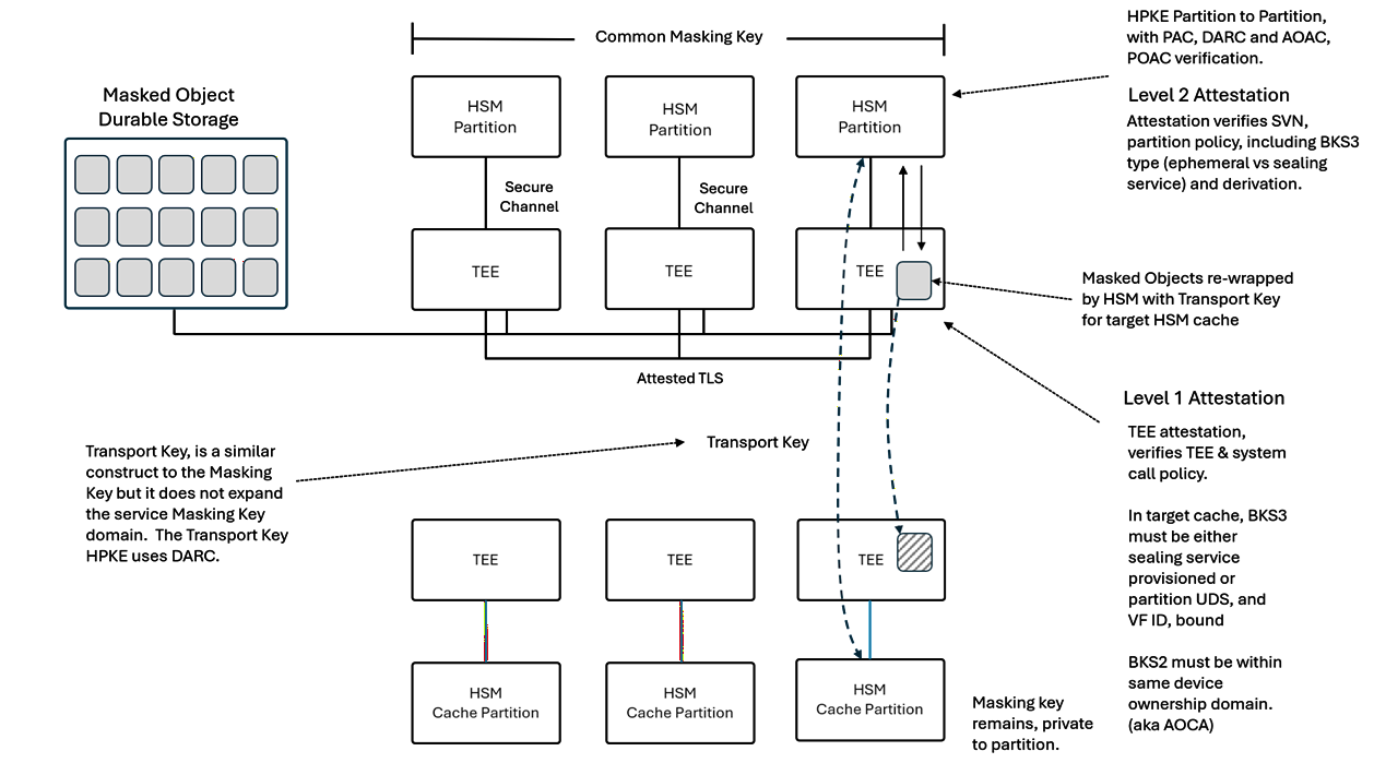
The security boundary is also extending. The SCMP workstream formally launched this summit aims to take trusted boot, attestation, control, recovery, and ownership lifecycle to rack and pod scale, reusing existing foundations. Today it is a workstream and an architecture goal — not a landed uniform interface. [36] A security control plane protects the hardware lifecycle — not just first boot — only if it covers updates, repair, and resale.
Tessera Integrated HSM is the summit's new open security project, spanning architecture, protocols, software, and firmware; the fully open silicon implementation is a follow-on direction, and certification targets are not completed certifications. [37] Such projects may lower the entry cost of hardware key services, but customers still need to distinguish implementation, isolation boundary, and physical protection level — a shared interface name is not enough.
For cloud services, security and availability must be designed together. Unavailable keys can stop compute from taking requests; an attestation outage can keep nodes from joining; a bad update can retire a whole batch of capacity. Acceptance should cover signed upgrades, rollback, ownership transfer, key revocation, and recovery — watching business throughput throughout. Open source helps audit and adaptation; it does not replace explicit vulnerability response, maintenance terms, and supplier responsibility.
10 Chiplets and Edge Give the Open Ecosystem Distinct Layers
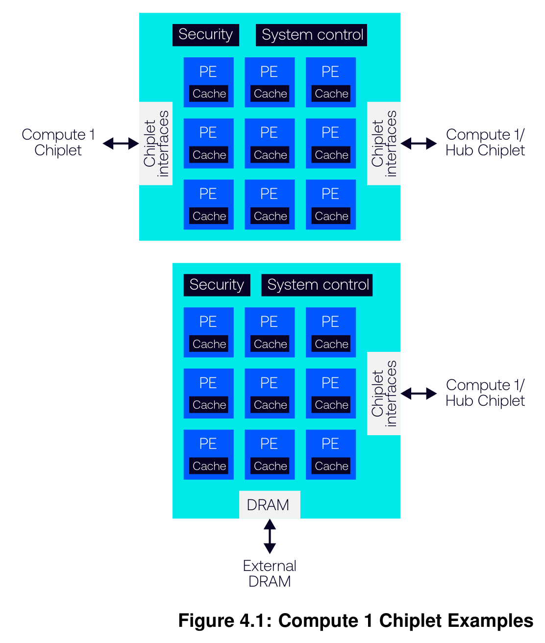
Chiplets, firmware, and edge computing complete the OCP panorama. FCSA's foundation architecture specification and BoW Flexi attempt a common base for modular silicon and interconnect; each document has its own scope and timeline — they are not all "new standards of this summit," and interfaces designed for lower-performance domains are not drop-in replacements for flagship accelerator interconnects. [38][39]
In engineering terms, chiplet standardization improves the starting point for cross-team collaboration, but a complete system still has to solve packaging, power integrity, thermal coupling, test, and yield. An electrical interface connecting does not mean software enumeration, error handling, and supply responsibility are aligned. For server companies, the near-term opportunity is feeding system requirements earlier into chip and package design — catching problems before whole-machine validation; entering the chiplet supply chain takes longer cycles and different capabilities.
Edge scenarios change the optimization targets again. OCP's AI Computing Continuum project targets regional rooms, enterprises, telecom, and industrial settings, emphasizing modular infrastructure under power, thermal, and space constraints. That is project scope and direction — not evidence that all edge products already share one mature standard set. [40]
An enterprise agent platform may care most about deployability in existing rooms, remote operations, and data boundaries; a regional cloud about stable power and expandable units; an industrial site also faces environmental conditions and field maintainability. Shrinking an MW-class rack does not automatically meet these needs. The open ecosystem's spread will more likely take the form of composable interfaces and management methods than one physical shape.
This also explains the players' strategies. Hyperscalers share infrastructure development costs through common specifications while keeping differentiation in workloads, silicon, and software; chip vendors open selected interfaces to widen what partners can build and integrate; ODMs and system vendors compete increasingly on validation, delivery, and service. Openness does not erase margin by itself — it moves value from isolated part specifications to the links that can own system outcomes.
Product teams should practice selective addition and subtraction. Add hot-plug, fault diagnostics, cross-vendor acceptance, and supply substitution capability; subtract configuration combinations that lack real-workload support. Multi-vendor becomes a usable choice only after a second source passes the same acceptance, firmware maintenance, and spares preparation. A compatibility list alone does not reduce real switching risk.
Appendix: Key Public Signals and Maturity
As of the information cutoff. The table distinguishes documents, demos, releases, and future-availability plans; "up to" keeps the original source's conditions and does not mean all maxima are simultaneously achievable.
| Item | Selected public metric | Status | Usage boundary |
|---|---|---|---|
| MGX 1.2 | Up to 250 kW | Partial design contribution this summit | Architecture support value, not practical power of every deployment [3] |
| Maia 300 | 96 accelerators, 167 kW | Production deployment planned from 2027 | Efficiency is projected; whole-rack throughput is not a per-chip metric [8] |
| AMD Helion | CPU-only up to 32,768 cores | In development, targeted available November 2026 | OCP contribution still planned; configuration maxima not additive [5] |
| Intel GPU D-series | ODM up to 480 GB LPDDR5X | Customer sampling | Intel's own card is 160 GB; not equivalent HBM throughput [7] |
| ESUN 1.0 | Operator network requirements spec | Published pre-summit, 1.1 in progress | A requirements spec is not a full protocol or volume interoperability [12] |
| USFP | 400 Gb/s per electrical lane; first batch planned at 16 full-duplex lanes | Form factor and plan announced this summit | Open spec and multi-source projects still pending [14] |
| Celestica DS6005 | 102.4 Tb/s CPO switch | System announcement this summit | Not evidence of wide volume production or multi-year field record [15] |
| Lightmatter CPO | 204.8 Tb/s switch platform | Production-validation platform | The four-XPU tray is proof-of-concept — a different status [16] |
| Diablo 400 | ±400 V or 800 V | v0.7 document public | Some connector items still open [19] |
| Delta Deschutes | 2 MW at 3°C approach | Shown, volume production planned Q1 2027 | On the press-release basis; compare at a unified operating point [25] |
| UQD v2.0 | Manual and blind-mate requirements merged | Effective September 22, 2026 | Cross-vendor mixing still needs deployment validation [23] |
| Samsung DCD CXL pool | TTFT down up to 38%, goodput up to 3.3× | Vendor-specific workload demo | Versus static allocation; not a general gain [29] |
| HBF v0.7 | Read-optimized near-NAND tier | Specification dated August 3, 2026 | Predates the summit; a spec is not measurement or volume evidence [32] |
| SCMP | Rack and pod security controls | Workstream formally launched this summit | Still an architecture goal, not a landed standard [36] |
| Tessera HSM | Open architecture, software, firmware | New project this summit | Fully open silicon and certification targets not yet achieved [37] |
Figure Sources and Usage Notes
Official figures retain original labels, structure, and necessary legends; figures taken from PDFs are cropped only to remove surrounding body text, with no redrawn content. Captions explain engineering relationships; ceilings, operating points, and case-specific values inside a figure do not automatically apply to other products. Equipment appearance and evaluation-connection figures are noted separately; logical relationships are not drawn into undisclosed physical structures.
Figures 11 and 15: Rolf Brink, Mohan J. Kumar, Steve Mills, Kelley Mullick, Thermal Boundaries in AI Infrastructure, OCP, 2026, v1.00. Taken from page 29 Figure 6 and page 19 Figure 4 respectively, cropped, content unmodified. Licensed CC BY-SA 4.0.
Other official figures come from the relevant vendors' and standards bodies' technical articles, product pages, specifications, or official specification repositories; provenance, image nature, and versions appear in each caption and in the references. Rights and licenses of the originals remain with their sources; the CC license above does not extend to other vendors' figures or to this report as a whole.
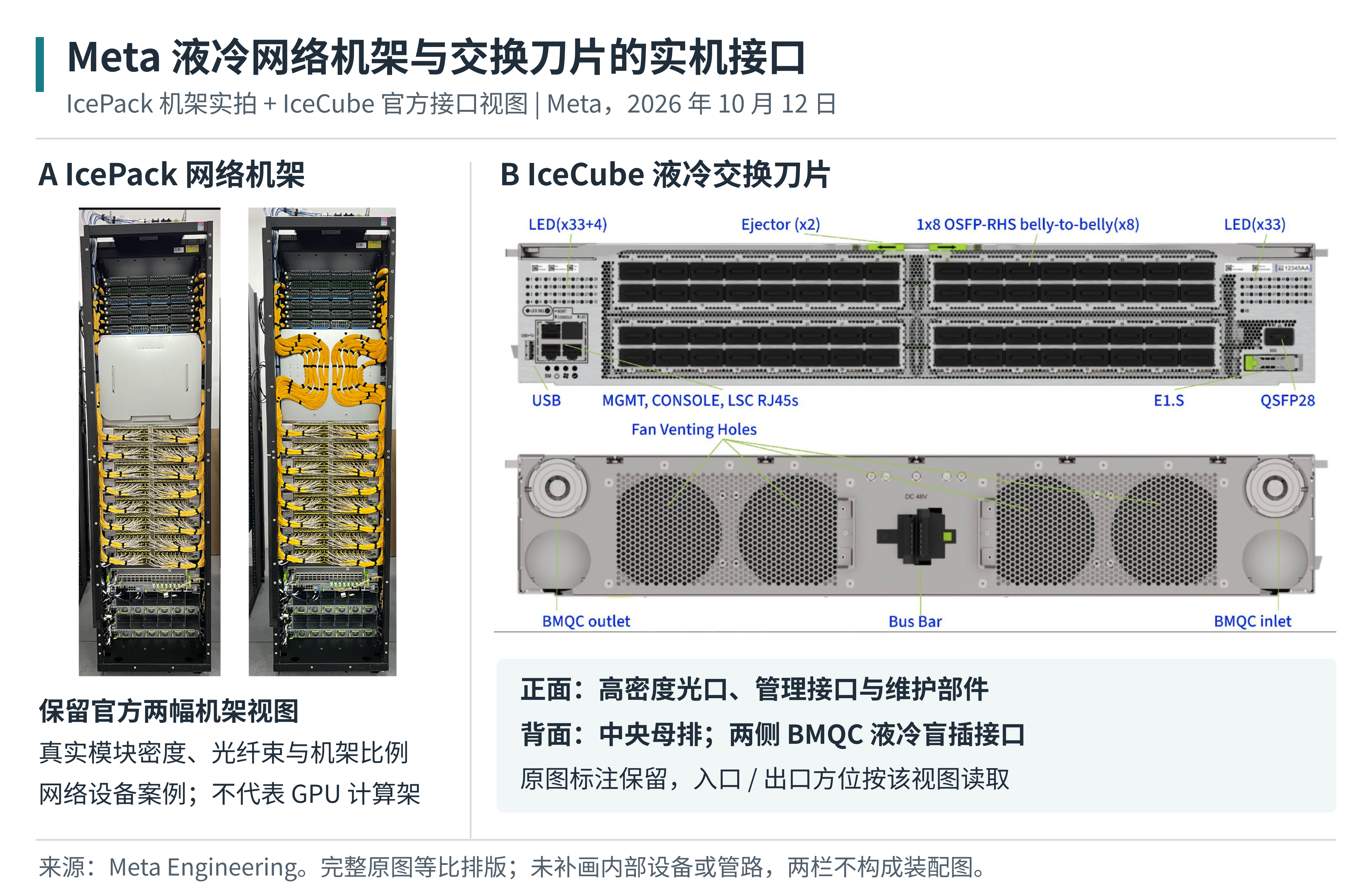
Figure 1 is arranged from Meta's official rack photographs and interface originals; Figure 16 shows official product appearances of models involved in evaluation materials; Figure 19 retains Samsung's original connection diagram. Images are shown at original proportions, with explanatory captions kept outside the figures; product photographs are not test-site photographs, and no invisible internal structure has been added.
References
Primary sources used by the body, figures, and appendix. Judgments remain as of the cover cutoff; supplementary figures use material already public beforehand and are not treated as summit announcements. Specification dates follow verified versions or effective dates. Links open the originals.
[1] OCP 2026 Global Summit official event information — OCP Foundation, 2026 event page
https://www.opencompute.org/events/ocp-summit/2026-ocp-global-summit/
[2] Realizing the OCP Open Data Center Ecosystem Vision — OCP Foundation, 2026 official overview
https://www.opencompute.org/news/realizing-the-ocp-open-data-center-ecosystem-vision/
[3] Vera Rubin MGX and DSX open contributions — NVIDIA, October 12, 2026
https://blogs.nvidia.com/blog/ocp-global-summit-vera-rubin-scale-ai-factories/
[4] OCP 2026 Lisa Su Keynote Takeaways — AMD, October 12, 2026
https://newsroom.amd.com/news/ocp-2026-amd-ceo-lisa-su-keynote-takeaways/
[5] Introducing AMD Helion Agentic AI Compute at Rack Scale — AMD, October 12, 2026
https://ir.amd.com/news-events/press-releases/detail/1301/introducing-amd-helion-agentic-ai-compute-at-rack-scale
[6] Arm AGI CPU Agentic Benchmarks — Arm, October 13, 2026
https://newsroom.arm.com/news/arm-agi-cpu-agentic-benchmarks
[7] Open Infrastructure for the Agentic AI Era — Intel, official OCP 2026 material
https://www.intel.com/content/www/us/en/newsroom/news/artificial-intelligence/intel-accelerates-open-infrastructure-agentic-ai-era.html
[8] Azure Maia multi-gigawatt deployment and Maia 300 announcement — Microsoft, October 12, 2026
https://blogs.microsoft.com/blog/2026/10/12/microsoft-to-expand-azure-maia-system-to-multi-gigawatt-deployments/
[9] Deep Dive into Azure Maia 300 Architecture — Microsoft Azure, October 12, 2026
https://azure.microsoft.com/en-us/blog/deep-dive-into-azure-maia-300-architecture/
[10] MRC Supercomputer Networking — OpenAI, May 5, 2026
https://openai.com/index/mrc-supercomputer-networking/
[11] OCP Summit 2026: Scale Up, Scale Out and Scale Across Networks — Meta Engineering, October 12, 2026
https://engineering.fb.com/2026/10/12/open-source/ocp-summit-2026-powering-ai-with-open-innovations-in-scale-up-scale-out-and-scale-across-networks/
[12] ESUN 1.0 specification release note — OCP Foundation, March 10, 2026
https://www.opencompute.org/index.php/blog/the-ocp-esun-10-specification-has-been-released
[13] UALink 2.0 Specification Release — UALink Consortium, April 7, 2026
https://ualinkconsortium.org/wp-content/uploads/2026/04/UALink-2.0-Specification-PR_FINAL.pdf
[14] NVIDIA and Cisco Introduce USFP — NVIDIA and Cisco, October 12, 2026
https://nvidianews.nvidia.com/news/nvidia-and-cisco-introduce-new-pluggable-optics-form-factor-to-scale-ai-factories
[15] DS6005 CPO Data Center Switch — Celestica, October 12, 2026
https://celestica.gcs-web.com/news-releases/news-release-details/celestica-introduces-ds6005-data-center-switch-co-packaged
[16] Open Rack CPO Switch and XPU Scale Up Server — Lightmatter press release, October 12, 2026
https://www.prnewswire.com/news-releases/lightmatter-delivers-open-rack-cpo-switch-and-xpu-scale-up-server-through-independent-collaborations-with-flex-and-other-industry-partners-302906361.html
[17] Integrated Optical Compute System Live Demonstration — Wiwynn with Ayar Labs and GUC, October 13, 2026
https://www.wiwynn.com/news/wiwynn-ayar-labs-and-guc-advance-co-packaged-optics-with-live-demonstration-of-integrated-optical-compute-system-at-ocp-global-summit-2026
[18] Optical Circuit Switching subproject — OCP Foundation, project page
https://www.opencompute.org/projects/networking/optical-circuit-switching/
[19] Diablo 400 v0.7.0 specification — OCP Microsoft Google Meta, effective March 1, 2026
https://www.opencompute.org/documents/ocp-specification-diablo-400-v0-7-0-final-pdf
[20] 800 VDC Power Architecture for AI Factories — NVIDIA, August 11, 2026
https://blogs.nvidia.com/blog/800-vdc-power-architecture-ai-factory/
[21] Open Data Center v0.7.0 — OCP AMD Google Meta NVIDIA, effective August 27, 2026
https://www.opencompute.org/documents/open-data-center-spec-revision-0-7-0-4-pdf
[22] Utility Grid Disturbance Performance Interface v1.0.0 — OCP Google Meta Microsoft NVIDIA, effective September 17, 2026
https://www.opencompute.org/documents/ocp-base-spec-interface-specification-between-hyperscalers-and-utility-grid-for-disturbance-performance-pdf
[23] Universal Quick Disconnect v2.0.0 — OCP Foundation, effective September 22, 2026
https://www.opencompute.org/wp-content/uploads/2026/10/OCP-Design-Spec_UQD_v2.0.0.pdf
[24] Single Phase Cold Plate Test Specification v1.0.0 — OCP Foundation, effective September 3, 2026
https://www.opencompute.org/wp-content/uploads/2026/10/OCP-Cold-Plate-Test-Specification-V1.0.0.pdf
[25] Grid to Chip Infrastructure at OCP Global Summit 2026 — Delta press release, October 8, 2026
https://www.prnewswire.com/news-releases/delta-to-showcase-energy-saving-grid-to-chip-infrastructure-solutions-for-sustainable-ai-at-ocp-global-summit-2026-302902203.html
[26] Rittal OCP 2026 RiMatrix HPC — Rittal, October 12, 2026
https://www.rittal.com/us-en_US/News/Rittal-OCP-2026
[27] Brazos Liquid Cooling for Air Cooled Data Centers — Google Cloud, June 16, 2026
https://cloud.google.com/blog/topics/systems/brazos-liquid-cooling-system-for-air-cooled-data-centers
[28] Thermal Boundaries in AI Infrastructure v1.00 — OCP Foundation, published October 12, 2026
https://www.opencompute.org/wp-content/uploads/2026/10/Thermal-Boundaries-in-AI-Infrastructure.pdf
[29] Samsung OCP 2026 showcase and agenda — Samsung Semiconductor, official event page
https://semiconductor.samsung.com/events/ocp-2026/
[30] BM1773 Ultra High Density Storage Solution — Samsung Semiconductor, product technical note
https://semiconductor.samsung.com/news-events/tech-blog/samsung-bm1773-ultra-high-density-storage-solution-for-ai-data-centers/
[31] LD4 series evaluation sample announcement — Kioxia, October 9, 2026
https://www.kioxia.com/ja-jp/business/news/2026/20261009-1.html
[32] HBF Architecture Specification v0.7.0 — OCP Sandisk SK hynix, August 3, 2026
https://www.opencompute.org/documents/ocp-hbf-architecture-specification-v0-7-0-final-pdf/
[33] Rack Management Service README — DSX AI Factory, read as of October 15, 2026
https://github.com/dsx-ai-factory/nv-rms
[34] Cluster Readiness Engine README — NVIDIA, read as of October 15, 2026
https://github.com/NVIDIA/cluster-readiness-engine
[35] Network Configuration Manager README — DSX AI Factory, read as of October 15, 2026
https://github.com/dsx-ai-factory/nv-config-manager
[36] SCMP OCP Workstream formal launch — Lattice and workstream partners, October 13, 2026
https://ir.latticesemi.com/news-releases/news-release-details/industry-leaders-formally-launch-scmp-ocp-workstream-open-secure
[37] Open Source Integrated HSM Technology — Microsoft Azure, October 13, 2026
https://azure.microsoft.com/en-us/blog/advancing-hardware-security-with-open-source-integrated-hsm-technology/
[38] Foundation Chiplet System Architecture v1.0.0 — OCP Foundation, effective February 2026
https://www.opencompute.org/documents/fcsa-1-0-0-pdf/
[39] BoW Flexi v1.0.0 — OCP Foundation, effective September 17, 2026
https://www.opencompute.org/wp-content/uploads/2026/10/bow-flexi_1p0_final.pdf
[40] AI Computing Continuum project — OCP Foundation, project page
https://www.opencompute.org/projects/aicc/
[41] Scaling AI Factories with Co-Packaged Optics for Better Power Efficiency — NVIDIA Developer, August 18, 2025, Figure 2 technical background
https://developer.nvidia.com/blog/scaling-ai-factories-with-co-packaged-optics-for-better-power-efficiency/
[42] G494 SB1 AAP2 GPU Server product page — GIGABYTE, no first-published date, read October 15, 2026
https://www.gigabyte.com/Enterprise/GPU-Server/G494-SB1-AAP2
[43] CMM D CXL Memory product page — Samsung Semiconductor, no first-published date, read October 15, 2026
https://semiconductor.samsung.com/cxl-memory/cmm-d/
[44] Breaking AI Memory Limits with CXL Memory Pooling — Samsung Semiconductor, page dated July 9, 2026, Figure 2
https://semiconductor.samsung.com/news-events/tech-blog/breaking-ai-memory-limits-with-cxl-memory-pooling/
[45] Optimizing KV Cache Offloading to CMM D in a CXL Switch based Memory Pool — Samsung Semiconductor, June 2026, Figure 2 page 7, configuration table pages 10–11
https://download.semiconductor.samsung.com/resources/white-paper/Optimizing_KV_Cache_Offloading_to_CMM-D_in_a_CXL_Switch-based_Memory_Pool.pdf
[46] Tessera Deployment Models Figure 16 — TesseraHSM official spec repository, October 9, 2026 commit bcdb7539
https://github.com/TesseraHSM/tessera-specs/blob/bcdb753953dbb0067a7764130e47b0d156adf6fb/Tessera – Deployment Models.md
[47] NVIDIA DSX OS: Modular Software for Operating AI Factories — NVIDIA Developer, May 31, 2026, Figure 2, pre-summit background
https://developer.nvidia.com/blog/nvidia-dsx-os-delivers-open-modular-software-for-operating-ai-factories-at-scale/
[48] Powering the Next Era of AI: Transition to LVDC — OCP Foundation, August 11, 2026, page updated September 24
https://www.opencompute.org/news/powering-the-next-era-of-ai-how-google-microsoft-and-nvidia-are-standardizing-and-accelerating-the-industry-transition-to-lvdc/
[49] Inside the NVIDIA Rubin Platform — NVIDIA Developer, January 5, 2026, page updated August 21, Figures 11 and 18
https://developer.nvidia.com/blog/inside-the-nvidia-rubin-platform-six-new-chips-one-ai-supercomputer/
[50] Resilient AI Supercomputer Networking Using MRC and SRv6 — OpenAI and coauthors, published May 5, 2026, page 2 Figure 1
https://cdn.openai.com/pdf/resilient-ai-supercomputer-networking-using-mrc-and-srv6.pdf
[51] The Evolution of Google's Jupiter Data Center Network — Google Cloud, August 23, 2022, historical background
https://cloud.google.com/blog/topics/systems/the-evolution-of-googles-jupiter-data-center-network