
OCP 2026: USFP and CPO Advance in Parallel
Optical interconnect choice depends on link bottleneck and service boundary
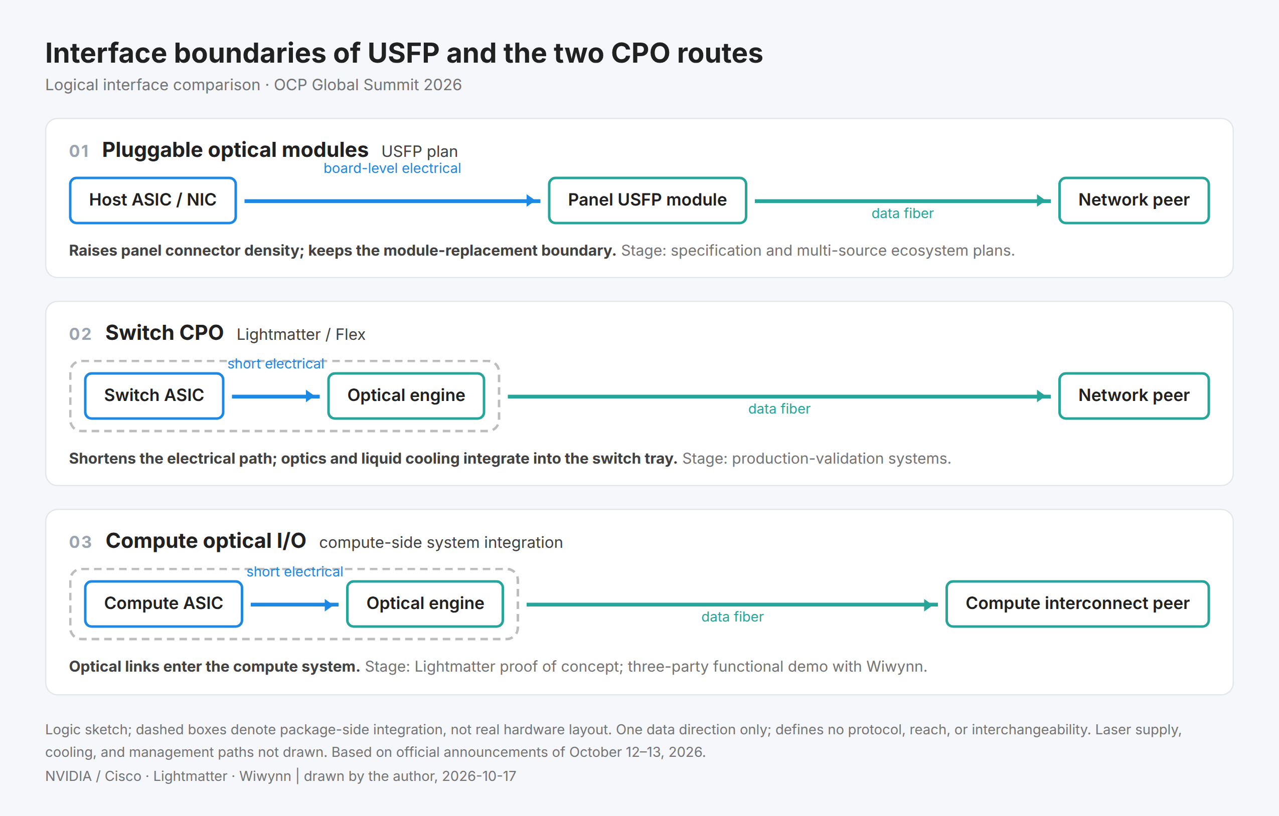
The optical interconnect progress at OCP 2026 is forming three routes aimed at different bottlenecks. Pluggable USFP wants to keep adding connectivity within limited switch faceplate space; switch CPO moves the electrical-optical conversion next to the switch chip, shortening the high-speed electrical path; compute optical I/O brings optical links near the compute package, serving accelerator-to-accelerator and intra-system interconnect. For enterprises building token factories, the choice should start from the constrained link, then ask which product boundary fits their deployment and service model.
On October 12, NVIDIA and Cisco announced the USFP form factor and ecosystem plan; the same day, Lightmatter published its production-validation switch tray with Flex and an XPU tray proof-of-concept from a separate collaboration. On October 13, Wiwynn, Ayar Labs, and GUC demonstrated an integrated optical compute system, validating optical-engine operation, telemetry, and system management on one platform. [1][2][3] The releases differ in maturity, but together they let customers discuss adoption far more concretely. Capacities, interface parameters, and acceptance fields are consolidated in the technical notes.
USFP continues the module service model
When switch faceplate space stops growing, raising connectivity by adding modules hits mechanical density limits; pushing per-lane speed higher puts signal-quality pressure on connectors and host electrical channels. USFP adjusts lane count, speed, and connector implementation together, trying to keep pluggable modules scaling. [1][9]
The appeal of this route is that modules remain separately purchasable, manageable, and replaceable units. For operations teams already built around faceplate modules — inventories and repair flows — it preserves a familiar service boundary. If higher density lets one switch terminate more endpoints, system designers may also drop devices added purely for port count. Whether that actually removes a network tier still depends on switch-chip capacity, port breakout, topology, and oversubscription — it cannot be derived from module capacity.
Adopting USFP starts with confirming host-side support. A footprint close to OSFP does not mean it works in existing OSFP ports; connector, electrical interface, host power, and thermal must each match. Upgrade plans for installed equipment should rest on a full compatibility statement and validation results, not on module dimensions.
Second, separate purchase timing from specification progress. NVIDIA and Cisco propose forming an open industry specification through a future community-led multi-source project; as of this article's date, USFP is a form-factor and ecosystem plan, not an OCP-approved standard. [1] The plan does not prove multiple modules are cross-validated or in volume supply. For customers who value the existing service model, the right move now is to check future platforms' connector and thermal roadmaps, then decide once specification, supply, and interoperability evidence are in.
Switch CPO shifts to whole-machine validation
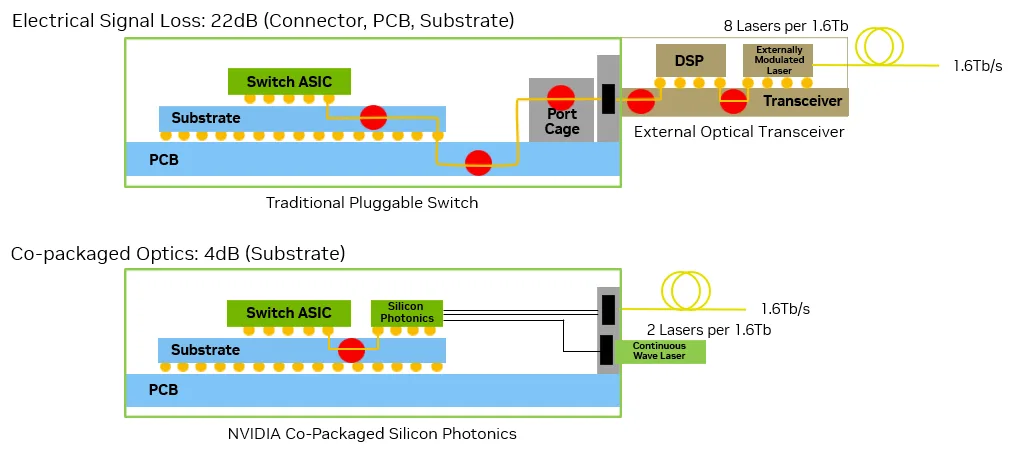
Pluggable modules sit on the faceplate, so the switch chip reaches them across board-level electrical channels and connectors. CPO places the optical engine next to the switch chip and lets fiber carry the long haul. [4] For new platforms where high-speed electrical links already constrain power, density, or signal quality, this offers an alternative design direction — and it means packaging, manufacturing, and service must be reworked together.
The Lightmatter-Flex switch tray is a concrete example from this summit. It integrates optical engines, an external light source, and liquid cooling into a tray oriented to standard rack and modular-server infrastructure, positioned as a production-validation system. [2] That stage says the project is exercising the manufacturing path; it does not yet prove volume output, customer deployments, or long-term reliability.
Why the manufacturing path matters is clearest in assembly. An optical engine working on a lab board and a system assembling reliably on a production line are different engineering problems. How fiber enters the package, what order the build follows, which interfaces can be opened, how the cooling structure makes room for fiber routing — all shape takt time, rework, and delivery. Adopting existing rack and server module boundaries lets system vendors discuss cabinet fit and supply-chain organization early, instead of redesigning the periphery after the photonics are done.
Where the light source sits shapes the whole machine as well. Lightmatter's Guide DR can sit inside the tray with an integrated cold plate. [6] "External" in external light source means external to the optical engine — not necessarily at the chassis faceplate. Internal light supply can free panel space while requiring the product to define how the source is swapped, how cooling disconnects, and how the supply path is managed. For customers planning switch CPO, these conditions belong in pilot acceptance alongside manufacturing yield and repair flows.
Compute optical interconnect first validates accelerator benefit
Compute optical I/O brings optical links next to the compute chip, addressing transfers inside compute systems and between accelerators. It shares photonic-integration technology with switch CPO, but the product object and validation tasks differ. Optical I/O does not by itself decide whether the link speaks Ethernet, some scale-up protocol, or an interconnect with particular coherence semantics; protocol, flow control, and software jointly determine end-to-end behavior.
Lightmatter's XPU tray comes from a separate collaboration with another ODM, using that ODM's modular-server infrastructure to show how an open silicon-photonics architecture enters a compute tray. [2] The system is positioned as a proof of concept. It is neither another configuration of the Flex switch tray, nor can its progress be merged with that tray's production validation into one volume-production conclusion.
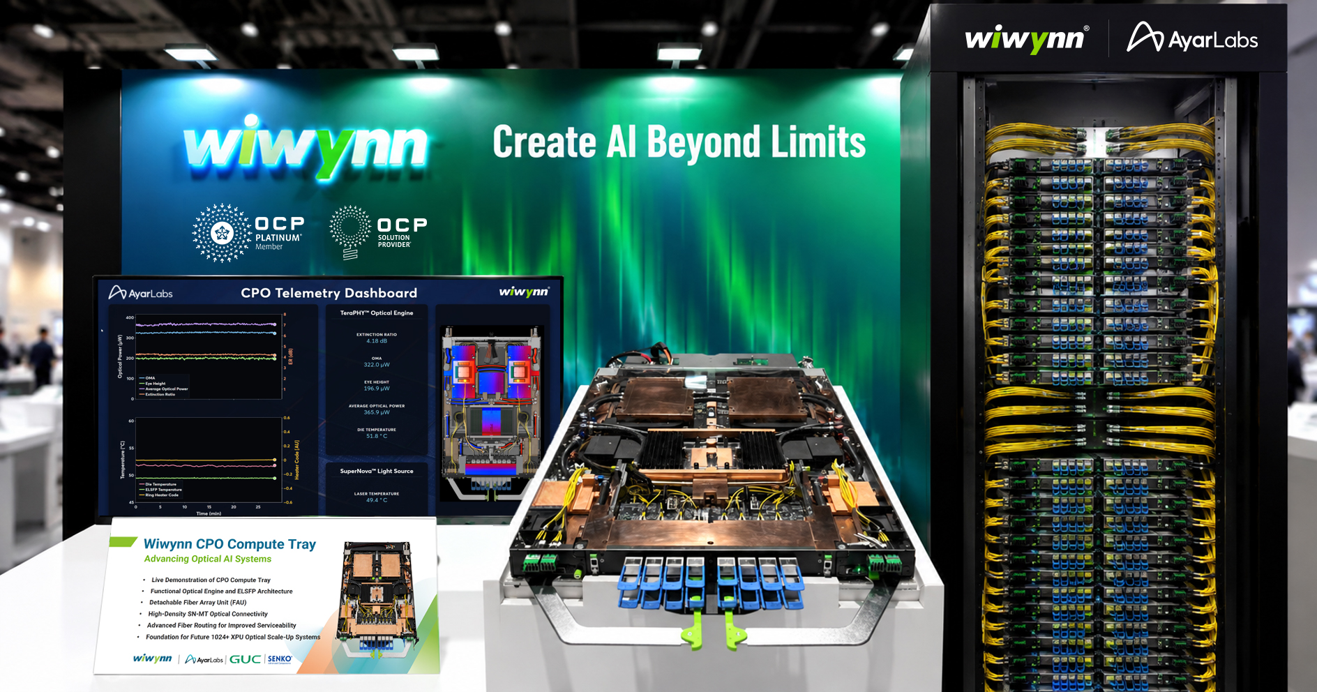
Wiwynn, Ayar Labs, and GUC focus on a running compute platform. The three integrated a multi-chip package, optical engines, and an external light source, continuously read optical-engine telemetry, and showed detachable fiber connection and in-chassis fiber routing. [3] Compared with the earlier rack-level architecture collaboration, this advances to platform integration and functional validation.
The value of running live is that constraints previously seen separately now appear together. Compute-load heat varies and hits optical devices; packaging and cold plates constrain fiber space; the system controller must recognize optical-engine and source states. A running platform lets the partners check whether these interfaces join, and lets customers raise system-management requirements. But link-up, readable telemetry, and stable metrics over one observation window still do not replace long-run statistics, volume yield, and failure-recovery testing.
Compute optical I/O is therefore best started from workloads with a clear interconnect bottleneck, validated jointly by compute-chip, optics, and system teams. Pilots must watch the physical link, protocol software, and job behavior together, confirming that added bandwidth lets compute resources complete more useful work. Seeing the optical interface reach target rate is not yet enough to decide how the whole compute platform migrates.
Trace failures along the light-supply path first
Understanding optical-interconnect operations, start with a light-supply anomaly. OIF's 2022 management white paper notes: when a supply fiber has trouble, the light source itself may not notice directly, but the optical engine can see it from input optical power and the host controller can coordinate handling. [7] This is not a failure that happened at this year's demo — it is the canonical scenario explaining the management need.
Follow that scenario: an operator seeing only "source healthy" can start troubleshooting in the wrong place. The management system must retain the mapping among light source, supply path, optical engine, and traffic ports, trace a consumer-side anomaly to the right path, and determine affected traffic before pulling anything. If multiple links share power, a controller, or a supply connection, a fault can hit them together; redundancy assessment must examine those common dependencies, not just count source modules.
With that tracing path in place, telemetry fields earn their use. Optical power detects supply changes; temperature and tuning activity show operating conditions; error counts and traffic state judge impact. Wiwynn's shown optical-engine telemetry and OIF's published external-light-source management interface provide, respectively, system-demonstration and management-specification grounding. [3][8] A specification existing does not mean the platform implements every field, nor that the customer's alarm system can consume them; fields and acceptance terms are in the technical notes.
After finding the fault, recovery must be possible. Faceplate modules, external light sources, optical sub-assemblies, compute boards, and whole switch trays can each be the replaceable unit. NVIDIA has previously described field-replaceable external light sources, showing co-packaging does not force every optical part to be replaced with the main chip. [5] Customers must still confirm how many links or compute resources one repair touches, how long recovery takes, and whether liquid cooling must stop, fiber must be opened, or the unit must return to the factory.
Pilots should put thermal-load variation, light-supply anomaly, management-controller loss, and post-maintenance retest into one validation, checking whether traffic derates or jobs interrupt. Optical engines, packages, light sources, and whole machines may come from different vendors; the buyer needs one responsible party able to collect complete logs, reproduce conditions, and organize failure analysis. The value of operational capability is turning a successful demo into a product that can scale repeatably.
Adoption routes should start from real bottlenecks
The three routes may enter products at different tempos, and more than one may live in the same AI factory. Systems constrained by faceplate density that want to keep the module service model can track USFP's interface and ecosystem progress; systems where the high-speed electrical path is the new switch platform's binding constraint can evaluate switch CPO and validate manufacturing and service flows with it; where accelerator interconnect binds, compute optical I/O deserves a joint pilot whose acceptance object includes real workloads.
After choosing a route, the next step is pinning "open" down to interfaces. A summit release, adoption of an OCP specification, and formal standards recognition are different levels of fact. Lightmatter conforming to existing rack and server module boundaries reduces duplicated integration work, but does not directly prove optical-engine interoperability. [2] Buyers need to know which interfaces have public specifications, which remain vendor-proprietary definitions, and which require joint validation — that is what determines future procurement and upgrade freedom.
Finally, compare on the same capacity, energy, and recovery basis. Module capacity, switch-tray capacity, and compute-tray aggregate bandwidth describe different objects; physical line rate is not sustained application throughput either. Shared light sources, extra cooling, and real utilization all belong in the budget; device efficiency cannot be booked as whole-machine savings. The technical notes keep parameter correspondences and an energy example for checking on one boundary.
The change most worth carrying from this summit into the next procurement and design cycle is that optical interconnect is organizing around deliverable systems. The module route needs a stable multi-source ecosystem; the switch route needs repeatable manufacturing and service processes; the compute route needs protocol, software, and workloads to validate the benefit together. Which route goes first should be decided by the specific constraint it removes and the evidence it can deliver.
Technical notes
USFP interface and capacity accounting
USFP stands for Ultra-Dense Small Form Factor Pluggable. The first wave targets switches and SuperNICs, providing 16 full-duplex lanes within an OSFP-sized footprint. The electrical interface target rises from 200 Gb/s to 400 Gb/s per lane. Cisco's same-day note makes the capacity roadmap explicit: 16 lanes correspond to 6.4 Tb/s aggregate; extending to 32 lanes corresponds to 12.8 Tb/s, with further lane-count growth planned. [1][9] The top capacity in the joint announcement should be read against that extension roadmap — not as first-wave configuration with transmit plus receive summed, and not as application goodput.
The connector uses a two-dimensional array and a two-stage insertion action — module first, then high-speed contacts — to improve high-speed contact behavior and insertion-force control. TE Connectivity and Amphenol are building the cage, connector, and module ecosystem. [1] A similar size to an incumbent form factor states one mechanical constraint; host compatibility still includes connector, electrical, power, and thermal.
The vendors claim, versus 200 Gb/s-per-lane pluggables, 4× bandwidth density and roughly 1.3× energy efficiency for the target design. The density comparison folds in both doubled lanes and doubled per-lane rate; the efficiency comparison does not mean a 30% whole-switch power reduction. The up-to-100 W module thermal support is a design envelope — neither a measured per-module draw nor a savings result. [1]
Concrete configurations of the announced systems
The Lightmatter-Flex switch tray is specified at 204.8 Tb/s, 1RU, using eight Passage bidirectional optical engines, lit by Guide DR, integrated in a liquid-cooled chassis on ORv3 and MHS foundations. The XPU tray from the separate collaboration uses another ODM's DC-MHS infrastructure, carries four accelerators and two CPUs, with the vendor specifying 102.4 Tb/s aggregate scale-up optical bandwidth, using Passage, Guide DR, and detachable vClick optical interfaces. [2] The former is a production-validation system and the latter a proof of concept; the two capacities describe different objects and cannot be ranked against module capacity either.
Guide DR product material describes it as an LNIC light-source module that drops into a NIC bay, with an integrated cold plate. [6] That form shows an "external light source" can live inside the chassis; evaluation still checks internal service and cooling-connection conditions.
The Wiwynn demonstration used GUC multi-chip packaging, Ayar Labs TeraPHY optical engines, and SuperNova external light sources; the demo also included detachable fiber-array units (FAU) and in-chassis fiber routing. [3] These configurations support "platform integration and functional validation"; they provide no volume yield, long-term reliability, or MTTR statistics. Instantaneous readings and rack appearance in the photo cannot prove actual topology scale or production throughput.
Engineering conditions for photonics integration and repair
Trace-out, package escape, and connectors between the main chip and faceplate modules all spend signal budget. Equalization, retiming, or signal processing needed to hit target BER add power and possibly latency. CPO shortens one stretch of the electrical path, but once optical engines sit next to high-value packaging, they constrain — and are constrained by — advanced packaging, test, and thermal design. [4] The parameters in Figure 2 apply only to NVIDIA's specific 200 Gb/s-per-lane, 1.6 Tb/s case.
The manufacturing flow must state when optical function is tested, when fiber attaches, how defective units are handled, and whether rework touches compute or switch chips. Capabilities that could previously be screened module-by-module outside the machine now move partly into package and system flows.
Detachable optical interfaces help separate fiber and chip assembly steps, but "detachable" alone does not decide field serviceability. Products should give connector cleaning and inspection requirements, loss distributions after repeated mating, tooling, and staffing. Only with those stated can one judge in-room replaceability and how the post-swap retest is done.
Telemetry fields and acceptance method
Fields listed in the Wiwynn announcement include TX heater activity, eye height, optical modulation amplitude (OMA), extinction ratio (ER), and optical-engine and external-source temperatures. [3] OIF's 2024 ELSFP CMIS implementation agreement separately provides a management basis for monitoring module temperature, supply, channel bias current, and optical power. [8] The two sets come from a demo announcement and a management protocol respectively; nothing licenses inferring the demo platform implemented the latter's full field set.
Formal acceptance should verify each field's unit, accuracy, sampling rate, event retention, and alarm thresholds — and whether they flow into the customer's monitoring system. Rising tuning activity on a still-up link may reflect shrinking margin; the cause must be judged with environment, light supply, and error counters together — a single curve cannot diagnose device aging. Records should map back to supply paths and traffic ports so that fault localization, impact assessment, and post-maintenance retest all use one set of information.
How to compare capacity and energy
Capacity comparison needs lane count, per-direction rate, aggregation scope, and whether protocol coding and error correction are included. Bidirectional totals are not unidirectional capability; summed port capacity is not any-to-any bandwidth. Once training collectives and inference requests enter a real topology, congestion, synchronization, and load distribution take over.
Energy should be bounded by the full link — light source, drivers, receivers, tuning, signal processing, and added cooling. How shared-source fixed power is apportioned, and what link utilization is, must be stated. Per-bit energy after a capacity increase cannot be compared against a predecessor's whole-machine power under a different load.
As an author-assumed example: at 100 Tb/s sustained goodput with matched statistical boundaries, saving 2 pJ per bit corresponds to about 200 W; at 8,760 hours per year, about 1,752 kWh. The example represents no announced product. Real clusters still need to separate fixed from load-dependent power and combine density, efficiency, and utilization to convert into benefit per unit of useful compute.
Open interfaces and supply-chain delivery
Interface verification proceeds layer by layer: chassis dimensions, optical connector mating, optical power and wavelength, link protocol, and management-software recognition. Each layer should list what is publicly specified, what follows an existing implementation agreement, what is vendor-proprietary, and what requires joint validation. Openness may hold at only one layer; a single label is not evidence for all.
Multi-source supply is judged per component. Two connector suppliers do not make two optical engines drop-in replacements; changing lasers can involve supply power, wavelength combinations, management fields, and safety procedures. Supply-chain deliverables should include validated firmware-version combinations, spare compatibility ranges, repair turnaround, and one responsible party for log collection, reproduction, and failure analysis of system-level issues.
Sources and caveats
Information as of October 17, 2026. This article labels 2026 product plans, production-validation systems, proofs of concept, and live functional demonstrations separately; 2022–2025 materials serve only as mechanism and management background. All vendor capacity and efficiency claims retain their original scope of applicability; no cross-vendor performance ranking was made across different aggregation bases. The energy example is the author's assumption. Figure 1 is the author's logical schematic; Figures 2 and 3 are official images with sources.
[1] NVIDIA and Cisco, NVIDIA and Cisco Introduce New Pluggable Optics Form Factor to Scale AI Factories, October 12, 2026.
https://investor.nvidia.com/news/press-release-details/2026/NVIDIA-and-Cisco-Introduce-New-Pluggable-Optics-Form-Factor-to-Scale-AI-Factories/default.aspx
[2] Lightmatter, Lightmatter Delivers Open Rack CPO Switch and XPU Scale-Up Server Through Independent Collaborations with Flex and Other Industry Partners, October 12, 2026.
https://lightmatter.com/press-release/lightmatter-delivers-open-rack-cpo-switch-and-xpu-scale-up-server-through-independent-collaborations-with-flex-and-other-industry-partners/
[3] Wiwynn, Wiwynn, Ayar Labs, and GUC Advance Co-Packaged Optics with Live Demonstration of Integrated Optical Compute System at OCP Global Summit 2026, October 13, 2026.
https://www.wiwynn.com/news/wiwynn-ayar-labs-and-guc-advance-co-packaged-optics-with-live-demonstration-of-integrated-optical-compute-system-at-ocp-global-summit-2026
[4] NVIDIA, Scaling AI Factories with Co-Packaged Optics for Better Power Efficiency, August 18, 2025, Figure 2 and related text.
https://developer.nvidia.com/blog/scaling-ai-factories-with-co-packaged-optics-for-better-power-efficiency/
[5] NVIDIA, How Industry Collaboration Fosters NVIDIA Co-Packaged Optics, August 26, 2025, external light source section.
https://developer.nvidia.com/blog/how-industry-collaboration-fosters-nvidia-co-packaged-optics/
[6] Lightmatter, Guide DR product page, undated, retrieved October 17, 2026.
https://lightmatter.com/products/guide-dr/
[7] OIF, Management of External Light Sources and Co-Packaged Optical Engines, OIF-MGT-Co-Packaging-ELSFP-01.0, November 1, 2022, section 8.2.
https://www.oiforum.com/wp-content/uploads/OIF-MGT-Co-Packaging-ELSFP-01.0.pdf
[8] OIF, Implementation Agreement for External Laser Small Form Factor Pluggable CMIS, OIF-ELSFP-CMIS-01.0, September 4, 2024, sections 8.2, 8.11.
https://www.oiforum.com/wp-content/uploads/OIF-ELSFP-CMIS-01.0.pdf
[9] Cisco, Cisco and NVIDIA Announce USFP: Expanding the Path to AI Connectivity, October 12, 2026, "Accelerating the next generation of AI fabrics" section.
https://blogs.cisco.com/news/cisco-and-nvidia-announce-usfp-expanding-the-path-to-ai-connectivity