
OCP 2026: Power Standardization for the AI Factory
Power design must join disturbance response and service recovery
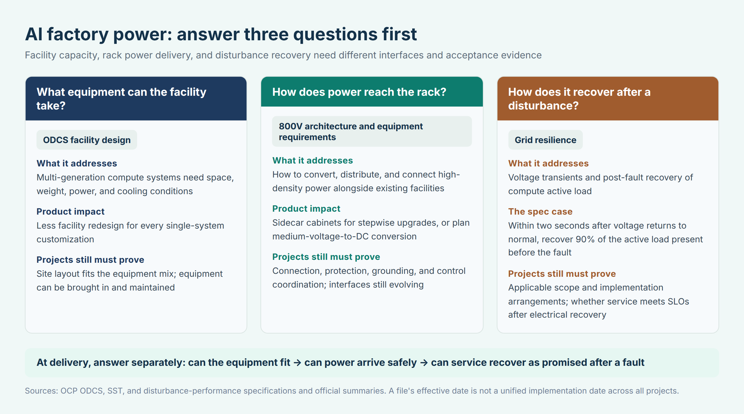
To build an AI factory, the power team and the compute team must first answer three questions: what equipment the facility can accommodate, how electricity reaches the rack, and how compute load recovers after a grid disturbance. These separately decide whether the building can accept the next-generation system, whether the power chain can sustain higher density, and whether the platform behaves predictably under anomalies.
The power progress gathered at the 2026 OCP Global Summit can be read along these three questions. ODCS provides common design boundaries for facility conditions; the 800V work advances power architecture and equipment interfaces; Grid Resilience agrees how load must behave under voltage disturbances. [1][2] The three address interlocking but non-substitutable problems: a room with enough space and a DC bus that can deliver power has not thereby passed voltage-ride-through validation, still less does it mean the user's token service recovers at the same time.
For a CTO, the most useful change is that these requirements increasingly can be written into vendor interfaces, configurations, and acceptance plans up front. The following sections explain product impact along facility, power, and recovery paths; versions, contributors, and the finer energy and training examples are concentrated in the technical appendices.
What facilities must set aside for multiple generations of compute
The practical increment of ODCS is extending facility design once aimed at a specific system into next-generation, multi-platform guidance. It removes Google-specific near-term tables, TPU pod expansions, and campus layouts, replacing fixed row lengths with modular design expressed as power density per foot. [3] The target given to facility suppliers is shifting from a machine room customized for one compute system toward space, power, and cooling conditions reserved for many systems.
This is not an abstract slogan. The document touches transport corridors, cabinet weights, room height, power blocking, and cooling-manifold accessibility. They decide whether, after one generation of servers exits, the next can enter the same building without redoing slabs, corridors, or overhead piping. The density in the document is a kW/ft linear-row measure and must not be read as per-square-foot density or per-cabinet power. A design firm that misreads the convention can be off by an order of magnitude on total facility capacity even with every equipment parameter correct.
For system vendors, a common boundary reduces repeated pre-sales design, but it does not eliminate field engineering. Civil, rack, electrical, and cooling teams should put their assumptions into one interface table: whether shipping weight equals operating weight, whether side-mounted power takes extra space, whether the manifold can be serviced without moving adjacent equipment. ODCS supplies a shared starting point; each project still converts it into signable configurations and drawings.
How 800V changes the path from grid to rack
The attention 800V receives has a direct physical reason. In a simplified comparison at equal active power, ignoring conversion losses, 200 kW over 50 V DC requires 4,000 A; over 800 V it needs about 250 A. If conductor resistance were then artificially held fixed, resistive loss would fall with the square of the current. Real designs change conductor cross-section, distance, insulation, and protection, so this cannot be converted into a facility-wide saving percentage, let alone send high voltage directly to the chip. [6]
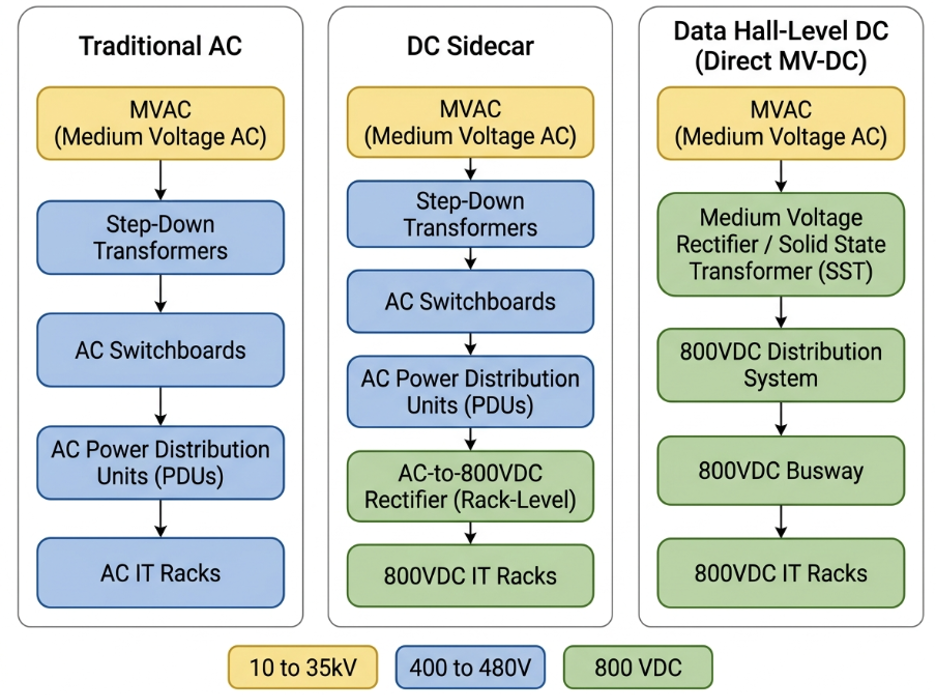
OCP had already published two migration paths in August. Existing rooms can place a power sidecar next to the compute rack, converting existing 480 V AC to DC; the longer-term path converts medium-voltage AC directly to 800 V DC and distributes across the data hall. The former still requires sufficient AC capacity and in-row space on site. The published Mt. Diablo ±400 V design and the later version planned for native 800 V must also be told apart — the same total potential difference does not mean compatible interfaces. [6]
SST v0.3 makes public the equipment requirements between medium-voltage input and 800 V output, giving electrical-equipment vendors a clearer development target; the LVDC white paper describes architecture choices and open questions. All important — but none is proof that every busbar, connector, protection scheme, and operating procedure has been unified. OCP's official summit summary still states explicitly that 800V-to-rack busbar and layout design is incomplete. [2][5] Vendors can start product development earlier; buyers should pin down which parameters are frozen and which interfaces may still move.
800V also lengthens the chain of responsibility upstream. Rack vendors must state allowed input ranges, fault isolation, and grounding conditions; conversion-equipment suppliers must characterize current limiting, startup, and recovery behavior; the facility must prove protection coordination and maintenance boundaries. For the customer, the valuable product is not a spec page reading "800V" — it is these interfaces validated together in one configuration. Whether swapping a power module or firmware version forces new dynamic testing should also be agreed before delivery.
After voltage recovers, how compute load should draw power again
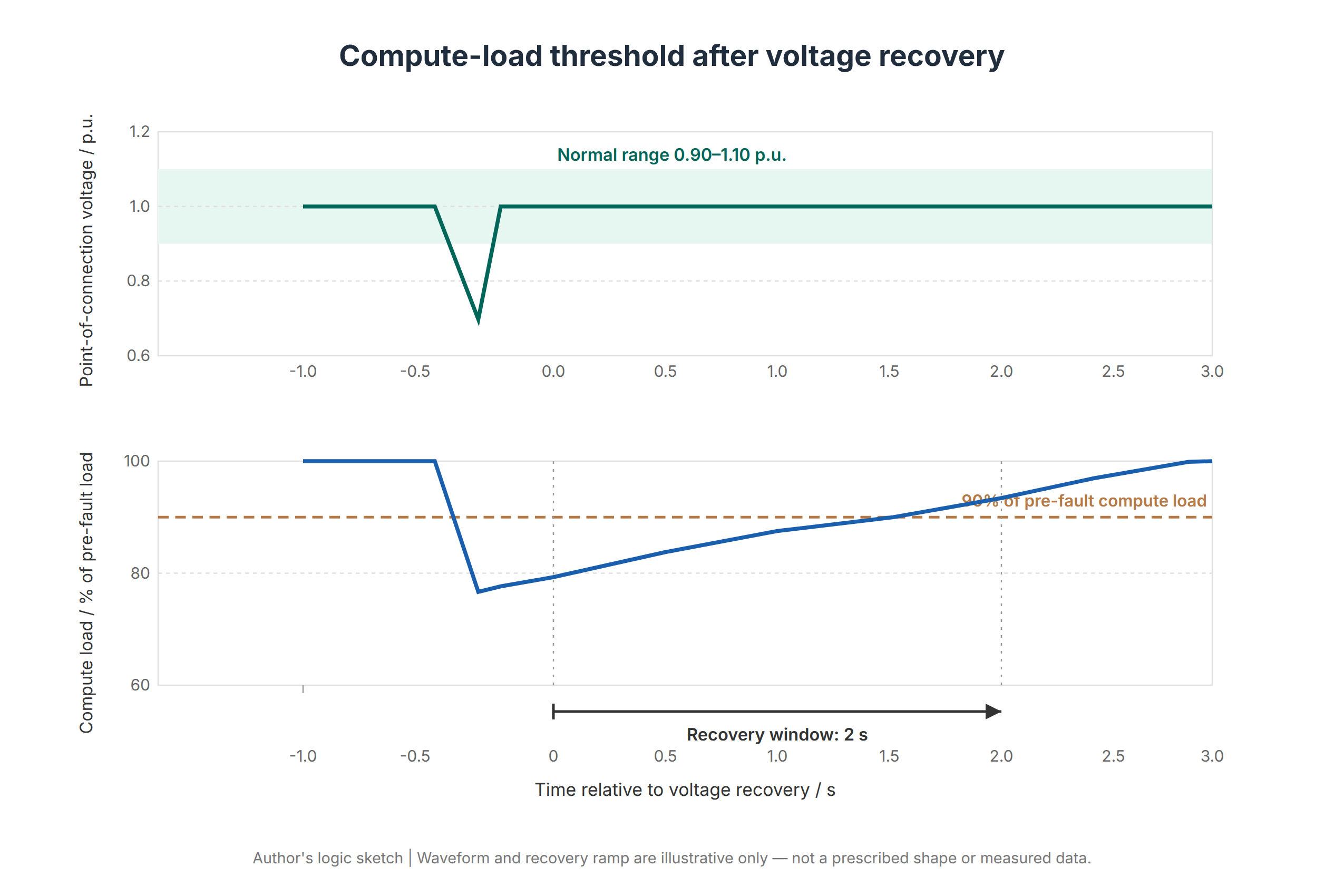
The grid-disturbance specification provides one explicit acceptance case. The Interface Specification Between Hyperscalers and Utility Grid for Disturbance Performance focuses on voltage ride-through and post-fault active-power recovery. Within the specified fault envelope, after voltage at the point of interconnection returns to 0.90–1.10 per unit, compute load must recover to 90% of pre-fault active power within two seconds. Per-unit takes rated voltage as 1.0. [4]
The two seconds start neither at fault inception nor at AI-service recovery; its object is compute load and must not be widened to facility-wide cooling and auxiliary systems. The specification also leaves ramp rates and forced oscillation to later work. [4] A common power language is being built item by item — not one document that answers every dynamic question. Projects still define applicable faults, measurement boundaries, and protection coordination in their interconnection conditions.
The September 17, 2026 date on the document is this version's effective date; it is not a mandate that all regions and projects comply from that day. Section 4.5 proposes phased adoption: set a separate implementation date for performance requirements, recommend that facilities already operating or already under interconnection agreements remain under grandfathered, non-retroactive terms for their lifetime, apply new terms only to growth beyond the original agreement, establish a voluntary best-efforts retrofit path for legacy sites, and expect new projects entering study or contract after the implementation date to comply at commissioning. [4] These are recommended frameworks; actual constraints remain set by the rules and interconnection arrangements each project is subject to.
Why should load recovery be constrained at all? A large compute load suddenly disappearing changes the grid's generation-load balance; staying on standby power long after voltage normalizes prolongs the imbalance. Servers staying powered and facilities meeting grid requirements are therefore two capabilities to be proven separately. For an operator, being granted 100 MW of interconnection capacity does not mean the draw behavior of those 100 MW can be changed at will.
After electrical recovery, the token service may still be recovering
Power acceptance and service acceptance should be recorded separately within the same event. Training should preserve state and communication groups where possible; interactive requests are more exposed to queue amplification. Even after power draw and equipment capacity recover, user experience can lag behind.
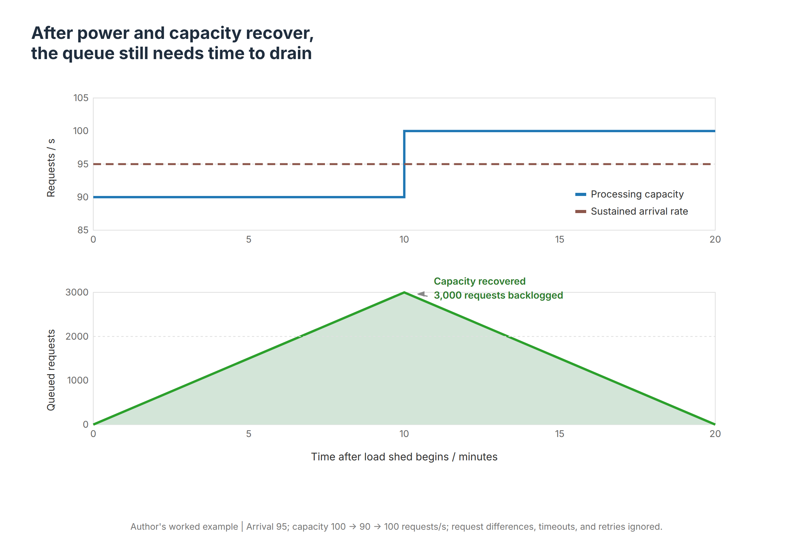
Offline inference can queue when deadlines allow, trading delivery time for electrical flexibility; interactive inference must hold first-token latency, inter-token latency, error rate, and tail latency. Suppose normal capacity is 100 requests per second with 95 arriving; derated to 90 processed, ten minutes builds a backlog of 3,000. After recovery to 100, only 5 per second clear net — another ten minutes to drain. The example ignores request-length variance, timeouts, and retries, yet it suffices: electrical compliance does not automatically equal service compliance.
Ride-through and demand response should also keep two independent paths. The former faces sudden electrical disturbances; the latter changes demand by agreement, with room for advance notice, migration, or load shifting. Google's machine-learning demand-response work with I&M and TVA is explicitly location- and reliability-constrained; NVIDIA's WPPS brings power profiles into BCM and Slurm workflows. [9][10] These are slower-timescale adjustment levers — they do not prove any request is interruptible at any moment, still less are they millisecond protection mechanisms.
From PSU to scheduler, control authority must be clear
Voltage excursions first meet rectifiers, PSUs, and local protection; above them sit UPS, battery storage, and facility control; on the compute side, GPU power control, rack management, and job scheduling. Each has different information and actuation speeds. Local protection may act before software sees an alarm; task migration still involves data, communication groups, and state recovery. A central scheduler cannot be asked to carry responses across all time scales alone.
Concrete time constants do not transfer across vendors. Acceptance should measure each layer's detection latency, command propagation, settling time, and default action on loss of communication — and check the slowest node. When the facility controller demands reduced power while the task scheduler demands restored throughput, who holds the final limit and how conflicts are arbitrated must be written into the control interface. Wiring several management APIs together does not make the control loop stable.
Open power changes the supply-chain division of labor
For power-equipment vendors, common requirements reduce per-customer rework — and push competition toward verifiable dynamic performance. Two devices with similar rated efficiency can behave differently in current limiting, anomaly recovery, and coordination with storage. Suppliers should deliver models, test conditions, and limitation statements so integrators can judge which behaviors are covered and which still need project-level validation; without these materials, open drawings can still become new integration black boxes.
For operators, facility life spans several compute generations; the value of common interfaces is preserving upgrade options, not guaranteeing free upgrades. Procurement can separate the stable from the replaceable: building and upstream capacity planned for the long term; conversion modules, rack connections, and control strategy delivered per version. If interfaces change later, contracts should name the replacement boundary, maintenance windows, and responsible party rather than leaving all compatibility risk to the next server program.
Software vendors gain new product space too, but on verifiable data. Power policy needs to know which customers carry hard latency commitments, which jobs can defer, which partitions have headroom; the facility side needs trustworthy execution feedback. A dashboard drawing power curves is not closed-loop control — only when trigger, execution, verification, and failure handling are all traceable does management software actually participate in delivering power capability.
Common specifications finally land in sellable capacity and clear ownership
The new delivery report should put point-of-interconnection voltage, active power, UPS and storage state, rack power, and task metrics on one time axis — recording firmware, protection settings, load composition, and initial battery state. Otherwise a successful recovery cannot be reproduced, and the power and compute teams may read cause and effect backwards. Repeated disturbances, loss of the management network, partial power withdrawal, and low storage reserve should enter joint testing.
Capacity economics change accordingly. Rated equipment count, granted interconnection capacity, and sellable capacity meeting service commitments need not agree. Multi-tenant platforms must distinguish guaranteed from interruptible capacity and agree allocation and deration records in advance; selling all regulation headroom and leaving users with unagreed performance loss is not acceptable. Investment returns should count interconnection progress, effective output, and recovery cost together — netting out storage consumption, extra cooling, and validation overhead.
The industrial significance of this year's progress is that common design conditions, equipment interfaces, and dynamic behavior are beginning to interlock. ODCS makes facilities easier to aim at multiple generations; 800V gives high-density power an evolution direction; Grid Resilience turns grid requirements into discussable acceptance language. Whoever converts these documents into versioned, responsibility-clear, retestable products is the one who can turn open infrastructure into the ability to deliver tokens steadily.
Technical appendix 1 The storage support window and the specification's recovery deadline
The following example compares power and energy only. Assume a compute partition normally draws 100 MW and needs local power to cover a 20 MW gap for 3 seconds. The 3 seconds count from when local power starts carrying the gap — an assumed support window. The specification's two seconds count from grid-voltage recovery and measure compute-load restoration; the two have no mandated equivalence.
If the gap is constant over 3 seconds, the energy is 20 MW × 3 s = 60 MJ, about 16.7 kWh; if it ramps linearly from 20 MW to zero, the triangular area gives about 8.3 kWh. The numbers correspond to no equipment test. Kilowatt-hours look small — converters, busbars, and protection must still deliver 20 MW to the right loads; the actual gap profile and required support duration come from system analysis.
Real configuration adds losses, temperature, aging, redundancy, and available state of charge. Does a battery normally used for peak shaving still have margin at fault time? Do load recovery and battery recharge stack into a new peak? NVIDIA's 2026 BESS design note treats state of charge, current limiting, and control priority as system problems. [8] Product teams therefore deliver megawatts, kilowatt-hours, and response behavior together — not a single battery-capacity number.
Retrofit cost must also be estimated per path. If existing PSUs or UPS cannot perform the required action, the solution may involve equipment replacement, control updates, and downtime construction; a firmware upgrade cannot be assumed to deliver ride-through. New projects can arrange margin from the interface stage; legacy sites must confirm the retrofittable boundary layer by layer. Common specifications reduce communication ambiguity; they do not erase the generational differences of physical assets.
Technical appendix 2 Training state and hardware power smoothing
Training, offline inference, and interactive requests absorb derating differently. In synchronous training, some devices slowing can drag the whole communication group; stopping introduces recomputation. With a ten-minute checkpoint interval, uniformly distributed failures, and the latest checkpoint available, the average recompute span is about five minutes — plus recovery and communication rebuild. This is a transparent conditional estimate, not a substitute for testing the actual training framework.
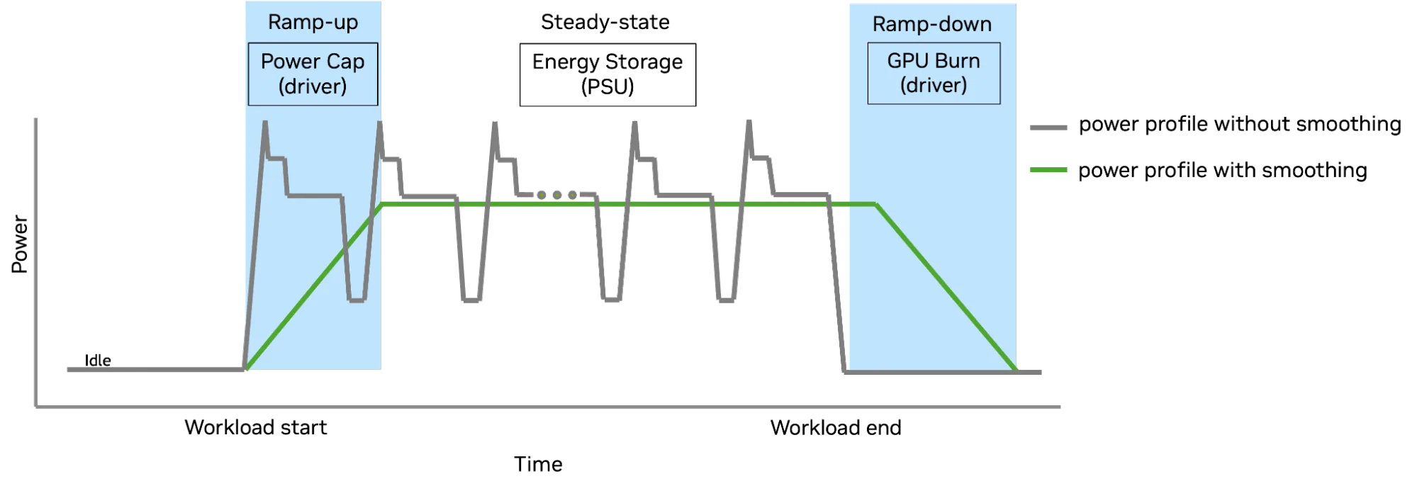
NVIDIA's 2025 GB300 NVL72 technical note uses power capping, PSU capacitive storage, and controlled GPU power draw to smooth load. [7] It shows compute hardware participating in shaping the upstream power curve; it is not evidence of compliance with this year's grid specification. In particular, energy consumed to smooth a downturn while producing no valid tokens must enter the efficiency account. A flatter curve and less energy per unit of useful output must not be conflated.
Technical appendix 3 Document versions and power-architecture maturity
ODCS v0.7 was developed with AMD, Google, Meta, and NVIDIA for 2027–2028 facilities. Its cover effective date is August 27, 2026, while the version history's 0.7 entry is June 23; both records are retained. Compared with the earlier Google-led version, it widens scope toward multiple compute platforms. [3]
Grid Resilience corresponds to the disturbance-performance interface specification v1.0.0, with Google, Meta, Microsoft, and NVIDIA participating; effective date September 17, 2026. Publication of the document version and adoption by each interconnection project are separate judgments; section 4.5's implementation suggestions do not automatically replace project terms. [4]
The 800V work includes the LVDC architecture white paper, equipment requirements, and project planning. The SST specification for medium-voltage-to-800V DC remains v0.3, cover effective date June 22, 2026, recorded in its version history as the first draft. Visionbay K-1 at the summit is an 800V factory plan for future Vera Rubin deployments and is not treated as operational. OCP also states that 800V-to-rack busbar and layout work remains open. [1][2][5]
Sources and caveats
Information as of October 17, 2026. Engineering examples and acceptance advice are the author's analysis. The ODCS cover reads August 27, 2026 while the version history's 0.7 entry reads June 23; both are retained, and this article does not treat the summit's concentrated release as every document first taking effect in October. 800V project plans are not treated as operational.
[1] NVIDIA, OCP Global Summit: Amid Ecosystem Adoption, NVIDIA Opens Vera Rubin Architecture to Help Scale AI Factories Worldwide, October 12, 2026.
https://blogs.nvidia.com/blog/ocp-global-summit-vera-rubin-scale-ai-factories/
[2] OCP, Realizing the OCP Open Data Center Ecosystem Vision, October 12, 2026, facility contributions and open future interfaces.
https://www.opencompute.org/news/realizing-the-ocp-open-data-center-ecosystem-vision/
[3] OCP, Open Data Center: Next-Generation ML Infrastructure Design Principles, Revision 0.7.0, version history and sections 3–6.
https://www.opencompute.org/wp-content/uploads/2026/10/Open-Data-center-Spec-Revision-0.7.0-4.pdf
[4] OCP, Interface Specification Between Hyperscalers and Utility Grid for Disturbance Performance v1.0.0, effective September 17, 2026, sections 4.2.2, 4.4.3, 4.5, and Table 1.
https://www.opencompute.org/documents/ocp-base-spec-interface-specification-between-hyperscalers-and-utility-grid-for-disturbance-performance-pdf
[5] OCP, Solid State Transformer Specification v0.3.0, cover effective date June 22, 2026, version history marked first draft.
https://www.opencompute.org/documents/ocp-sst-design-specification-v0-3-final-pdf/
[6] OCP, Powering the Next Era of AI: How Google, Microsoft and Nvidia Are Standardizing and Accelerating the Industry Transition to LVDC, August 11, 2026, migration-path diagrams and interface work scope.
https://www.opencompute.org/news/powering-the-next-era-of-ai-how-google-microsoft-and-nvidia-are-standardizing-and-accelerating-the-industry-transition-to-lvdc/
[7] NVIDIA, How New GB300 NVL72 Features Provide Steady Power for AI, July 28, 2025.
https://developer.nvidia.com/blog/how-new-gb300-nvl72-features-provide-steady-power-for-ai/
[8] NVIDIA, Designing Production-Ready Battery Energy Storage Systems for AI Factories, June 10, 2026.
https://developer.nvidia.com/blog/designing-production-ready-battery-energy-storage-systems-for-ai-factories/
[9] Google, How we're making data centers more flexible to benefit power grids, August 4, 2025.
https://blog.google/innovation-and-ai/infrastructure-and-cloud/global-network/how-were-making-data-centers-more-flexible-to-benefit-power-grids/
[10] NVIDIA, Workload Power Profile Solution Introduction, Mission Control 2.0.0 administration docs, updated July 16, 2026.
https://docs.nvidia.com/mission-control/docs/systems-administration-guide/2.0.0/wpps/introduction.html