
OCP 2026: Liquid-Cooling Interface Standardization
Maintenance scope and recovery time decide the compute hours you lose
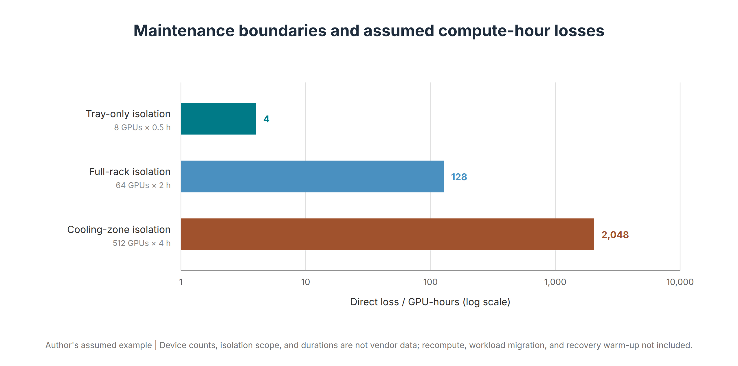
Replacing one compute tray: why does one design lose 4 GPU-hours, another 128, and another 2,048? Assume a tray with 8 GPUs and half an hour for isolation and recovery — the loss is 4 GPU-hours. Shutting down a 64-GPU full rack for two hours is 128 GPU-hours; shutting down a 512-GPU cooling zone for four hours is 2,048. All counts, topologies, and durations here are assumptions for comparing maintenance boundaries — not an MGX product commitment.
For a token factory, whether open liquid cooling helps comes back to this question: to replace one board, how much compute must stop, and how long until it recovers? A quicker-disconnect coupling shortens only one step. Fault localization, branch isolation, spare matching, retest, and rejoining the cluster all shape the total loss.
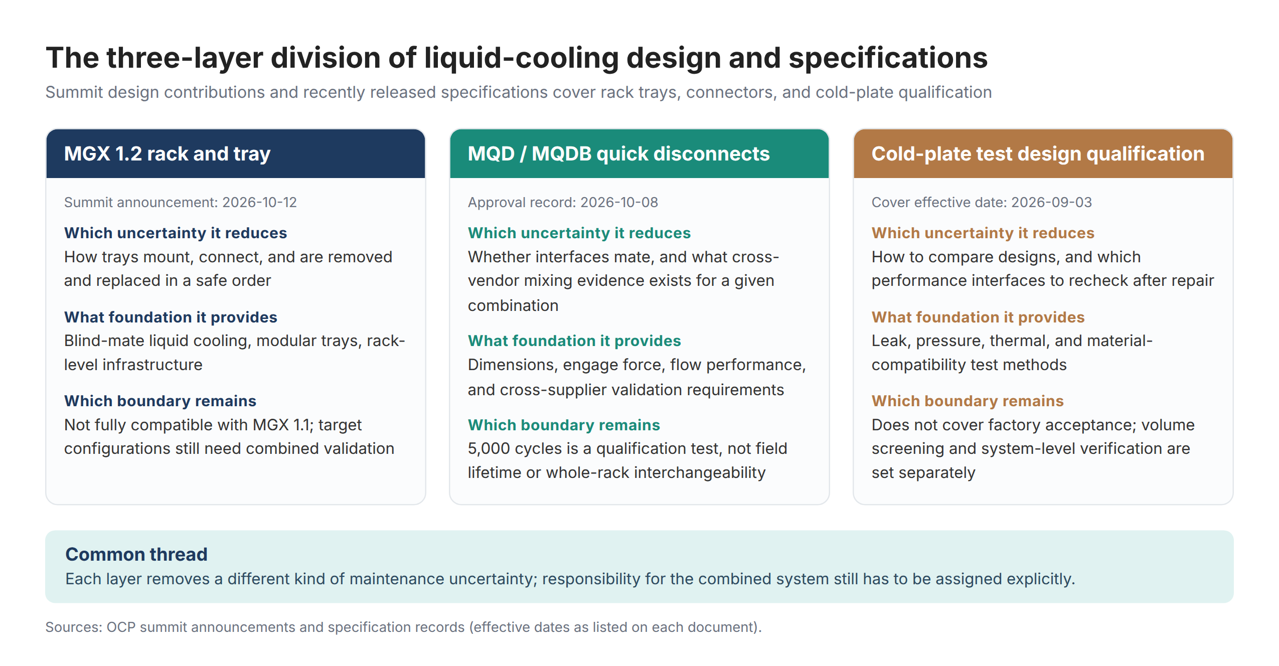
This year's MGX 1.2 rack and tray contribution, together with the recently published MQD/MQDB quick-disconnect and cold-plate test specifications, respond to this maintenance question from three angles: assembly, mating interoperability, and design validation. [1][2][3]
At the 2026 OCP Global Summit, NVIDIA contributed the Vera Rubin rack and compute-tray designs under MGX 1.2. Specifications available to the industry in the same period include MQD/MQDB v1.0.0, approved October 8 per its version history, and the Single-Phase Direct-to-Chip Cold Plate Test Specification v1.0.0, effective September 3 per its cover. [1][2][3] They each reduce one of three uncertainties: how equipment is installed and serviced, whether connector combinations mate reliably, and how cold-plate designs are validated. Internal date inconsistencies in the two PDFs are covered in the sources note.
These three layers of work do not unify every liquid-cooling interface, and "OCP-compliant" alone does not certify a cross-vendor interchangeable rack. What they provide is a more concrete design and validation foundation; system vendors still must convert that foundation into bounded, drillable repair capability.
MGX 1.2 reduces uncertainty in assembly and maintenance sequencing
NVIDIA stated this year that MGX 1.2 adds native 19-inch support, rack-level blind-mate liquid cooling, 5,000-amp liquid-cooled busbars, and support for racks up to 250 kW. [1] These are platform design capabilities: peak capability does not transfer automatically to every cabinet labeled MGX, nor does it certify that every supplier variant is in volume production. For manufacturers, a unified tray and rack infrastructure can reduce duplicate design; for operators, the value still depends on how the specific configuration is validated.
More notable than choosing cold plates, tubing, or connectors one by one is that cross-layer interfaces are starting to connect. When a tray slides into a rack, mechanical alignment, power connection, fluid engagement, and management state must coordinate — and disengage in a safe order during maintenance. Blind-mating only makes some of those actions more repeatable; the whole machine still must define when power-on is allowed, how an incomplete engagement is detected, and who blocks the device from entering operation on an anomaly.
Compatibility in particular needs version discipline. The MQD/MQDB specification states explicitly that these interfaces are for MGX v1.2.0 rack and tray designs, which derive from MGX 1.1 but are not fully compatible. [2] That sentence describes a boundary between MGX designs — it must not be simplified into "the new coupling fits all old racks." A real retrofit checks space, travel, power, and fluid interfaces item by item; miss one dimension and "reusable" becomes on-site rework.
Back to the opening comparison of GPU-hours: the MGX framework provides the design basis for narrowing replacement scope, but whether one tray alone can be stopped still depends on the target configuration's isolation, power, and management states working together. System procurement should be governed by the specifications, drawings, and test reports frozen at delivery.
MQD and MQDB reduce uncertainty in mating and interoperability
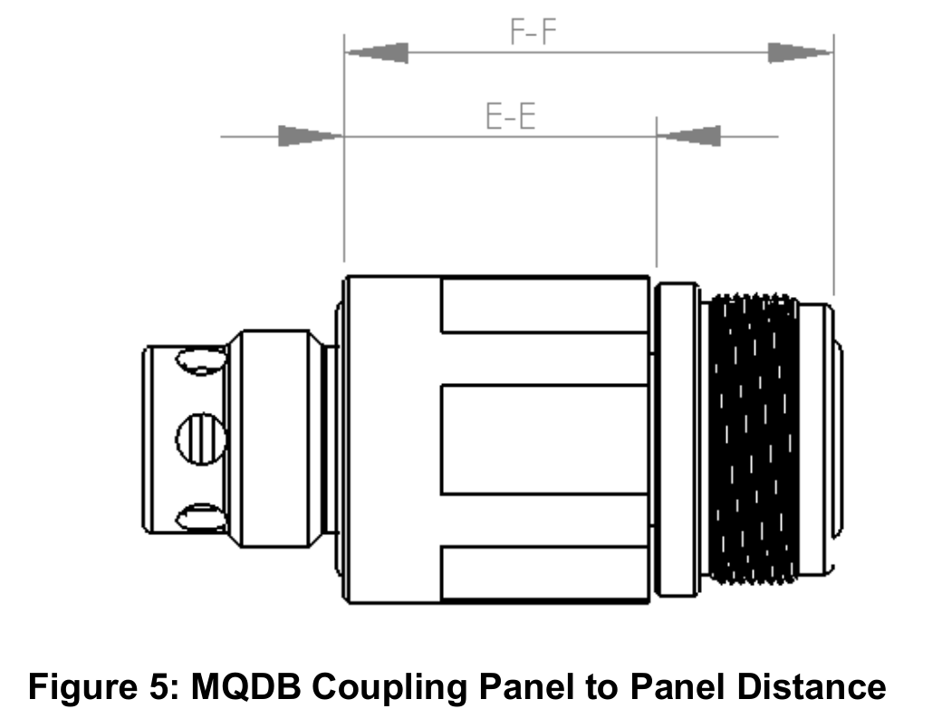
MQD stands for MGX Quick Disconnect; MQDB is the blind-mate variant, for nonflammable single-phase water or water-glycol and water-propylene-glycol systems. The specification publishes dimensional boundaries, connection force, flow performance, and validation methods, and requires cross-validation of supplier combinations at the same nominal size. [2] Purchasing used to stop at interface names and similar outlines; the more valuable change now is that buyers can demand evidence for specific plug-and-socket combinations.
Blind-mating also pushes requirements onto whole-machine tolerances. A manual coupling lets a person see the interface, adjust posture, and confirm locking; blind-mating hands those actions to guides, float mechanisms, and tray travel. Slide-rail clearance, chassis deformation, tube reaction force, and the insertion force of multiple couplings all accumulate. A coupling that mates smoothly on a bench does not guarantee a reliable seal and flow in a fully populated cabinet.
Connector reports and target-tray validation must therefore coexist. The state to rule out is a tray fully locked while a coupling never reached its effective engagement position; pull-test cycles must also confirm insertion does not transmit excessive lateral force to sealing surfaces. The dimensions and tolerances in the specification are design inputs; field staff cannot compensate for system deviation by pushing harder. The simpler maintenance is meant to be, the more the design phase needs explicit guiding, keying, and engagement-state feedback.
Sealing and flow must be checked separately too. No drips does not rule out a valve not fully open, contamination, or extra flow resistance from local stress; normal initial flow does not replace post-cycling seal validation. For system-management software, temperature alarms are only the last line of detection — engagement position, branch flow, and pressure change provide earlier signals. Sensor placement and thresholds come from platform validation, not from packaging them as a uniform configuration the specification already mandates.
What cross-validation provides for spare-parts interchangeability
MQD/MQDB requires each supplier to cross-validate with at least three other suppliers and to publish successful-validation lists and reports for end users. [2] That gives multi-source procurement a more concrete basis, but conclusions bind to the tested combinations, sizes, materials, and versions. One qualified product from a vendor does not cover all its part numbers and later changes; one mating pair passing does not prove the two vendors' CDUs, manifolds, and servers work reliably together long-term.
Buyers therefore need a maintained compatibility list, not a brand whitelist. When seals, molds, surface treatments, or fluid formulations change, the system vendor should state whether existing reports are affected and which items need retesting. Open interfaces can widen supply sources — and simultaneously require clarity on who owns combination validation and final system responsibility, so that parts makers each proving themselves individually does not leave all the gaps to field operations.
The 5,000-cycle mechanical insertion test in the specification is a qualification requirement under stated conditions; it converts neither into field lifetime nor into a guaranteed fault-free interval. [2] Real service adds long dwell, thermal cycling, fluid chemistry, and contamination. Qualification testing, factory acceptance, and in-service inspection are designed separately; cycle counts prove one class of test behavior and do not substitute for the other evidence.
Cold-plate testing reduces uncertainty in performance comparison and fault diagnosis
The single-phase cold-plate test specification addresses design and prototype qualification, covering leakage, pressure, thermal resistance and flow, mechanical, material compatibility, and cleanliness. It does not cover factory acceptance, production sampling, or per-unit screening. [3] That scope matters: system vendors can compare candidate designs by a common method, but purchase contracts must still define production release, defect screening, batch traceability, and change-based retest — "tested per OCP" does not mean every delivered plate passed every test.
Nor does the test method dictate one internal channel, material, or structure. It provides a comparable validation basis while preserving vendor design space in performance and manufacturing. For a CTO, the measure of effective openness is how much testing carries over when a new supplier is introduced and how many failure boundaries need re-proving — not how many times "open" appears on a bill of materials.
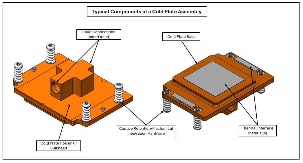
Cold-plate installation also involves thermal contact and mechanical loading at once. No leak after a repair does not mean TIM contact is restored; normal temperatures for a while do not cover later thermal cycling. Maintenance records should state which materials were replaced, with what assembly process, and how fluid and thermal performance were each retested. Collapsing both recoveries into one "replacement complete" state makes slow degradation impossible to trace.
The real repair boundary runs along the whole fluid path
Heat travels from the chip through TIM into the cold plate, then out through quick disconnects, branch lines, manifolds, and the CDU. A cold-plate leak, a manifold leak, a pump failure, and a shared-controller failure each need different isolation actions. "Dual pumps" on a bill of materials describes part count, not proof that control, power, and common plumbing are free of single points of failure. Repair scope is decided by the actual valves, plumbing, and control logic together.
If a product promises tray-only withdrawal, it must prove that the branch isolates independently, that other branches still receive sufficient flow, and that alarm policy does not escalate a local repair into a full-rack shutdown. If the site must close a common upstream valve, the real blast radius already exceeds the tray. Preserving the rest of the equipment fluidically is not business-loss-free either: a synchronous-training communication group may span the failed tray and still pause, regroup, or recover.
Delivery reports should therefore record both the hardware scope that lost cooling and the task scope affected. The former governs mechanical and electrical isolation design; the latter governs scheduling and spare capacity. A vendor-approved hot-pluggable connector does not mean the server can be pulled in any running state — maintenance follows the whole-machine approved safety procedure, drilled under real load.
Maintenance isolation must not break the remaining branches' cooling
Closing one branch during repair changes the operating point of the rest. Even with qualified quick disconnects and cold plates, the system vendor must still prove that after local isolation, flow, pressure, and temperature of remaining equipment stay within bounds. Full conditions and computation for the hydraulic example are in the technical appendix; the key conclusion is that more total flow can also mean more pump power, and CDU total flow cannot replace branch validation.
Meeting total flow can hide branch imbalance: a low-resistance branch takes excess fluid while a high-heat branch starves, and the CDU total still looks fine. Cold plates, quick disconnects, hoses, and manifolds must be evaluated as one hydraulic network; closing a branch for maintenance, switching in a standby pump, or a local blockage each shift the operating point. Open connectors reduce some uncertainty; they do not cancel system-level flow and pressure-drop validation.
Vertiv's single-phase technology cooling deployment guide emphasizes supply-return isolation, venting, and filtration at the CDU and heat-load connections, and cleaning before IT attach. [4] Those established practices should enter new platforms' delivery plans; otherwise racks and couplings can meet specification and still suffer thermal faults from out-of-spec site fluid condition. Facility and server teams should sign off fluid-path conditions jointly rather than each watching only its own gauges.
Materials, cleanliness, and spares form long-term interfaces
Coolant touches a full material chain: cold plates, couplings, solder, tubing, seals, and tooling residues. One qualified metal or elastomer does not certify a mixed loop compatible long-term in real fluid and temperature. Changing suppliers — even with identical external dimensions — can shift corrosion, leachables, or seal behavior. The cold-plate specification's material and fluid compatibility validation exists to be combined with the actual system list. [3]
Cleanliness does not end at the factory either. OCP's Modular Technology Cooling System guide discusses pre-cleaning, running-fluid introduction, and controls for bringing later equipment online. [5] A new server joining a shared loop needs fluid acceptance independent of compute performance; one uncontrolled maintenance contamination can turn a local replacement into a multi-plate problem. Records should keep who opened the loop, with what cleaning and capping, and the confirmation before reconnection.
Spares have shelf states too. Dust caps, seal revisions, storage conditions, and fluid requirements follow supplier rules. How long-stocked components return to service, and whether refurbished parts enter the same pool, should be defined by the system vendor. Otherwise the combination improvised for an urgent repair can land precisely outside the cross-validation reports. The dividend of open procurement should be manageable alternative sources — not unlimited mixing.
Turning maintenance boundaries into availability commitments
The opening 4, 128, and 2,048 GPU-hours measure direct impact, not complete financial loss. Synchronous-task recomputation, model warm-up, request migration, labor, spares, and contractual penalties can add cost; idle equipment does not necessarily cause equal revenue loss. Enterprises should measure physical impact first, then combine with real utilization and contribution margin. Finer isolation has its own price: more valves, couplings, and sensors mean more potential leak points, pressure drop, manufacturing cost, and spare types.
The earlier OAI liquid-cooling guidelines already discussed whole-board-plus-loop, multi-module, and single-module FRU boundaries — design options, not field capabilities every platform supports. [6] Whether the new specifications create value depends on system vendors choosing these boundaries and counting waiting for staff, localization, spare retrieval, isolation, swap, refill-and-vent, retest, and rejoin into recovery time. Minutes of bench insertion do not substitute for an annual service commitment.
The most promising outcome of this year's liquid-cooling openness is therefore a maintained, versioned, combination-evidenced, drillable service system. MGX 1.2 supplies the rack and tray framework; MQD/MQDB makes fluid-connection promises concrete; cold-plate testing gives design comparison a common basis. The last mile still belongs to the system product: when a fault happens, how much compute stops, who owns localization and recovery, and whether post-recovery token cost stays predictable.
Technical appendix Conditional derivation of hydraulic demand and pump power
A transparent example. Assume 100 kW of heat entirely into the water loop, specific heat 4.18 kJ/(kg·K), supply-return ΔT of 10 °C: the flow is about 2.39 kg/s, roughly 143 L/min at 1 kg per liter. With glycol or propylene-glycol mixtures, use the properties at the actual temperature and concentration; do not carry over these numbers.
If the ΔT target halves to 5 °C, flow roughly doubles. Further assume pressure drop varies with flow squared in the relevant range and pump efficiency is constant: pump input power rises roughly eightfold. A loop at 100 kPa differential and 50% efficiency draws about 478 W at 143 L/min; the doubled-flow simplified model gives about 3.8 kW. It is not a vendor pump curve, but it shows that "higher flow" at an interface does not by itself prove a more efficient system.
The heat balance uses mass flow = heat load ÷ (specific heat × ΔT); pump input = differential pressure × volumetric flow ÷ efficiency. 143 L/min ≈ 0.00239 m³/s, so 100,000 Pa × 0.00239 ÷ 0.5 ≈ 478 W. At doubled flow with fourfold assumed differential pressure and twofold flow, pump power reaches eightfold. Real loops have varying flow regimes, valve states, and pump-efficiency shifts; procurement and acceptance should use measured curves at the actual operating points.
Sources and caveats
Information as of October 17, 2026. Hydraulic and outage examples are the author's assumptions; maintenance advice is not a new specification clause. The MQD cover prints "Effective Oct 8, 2024" while the version history records OCP steering-committee approval on October 8, 2026, and the footer prints 2026; this article follows the version-history reading and discloses the editorial inconsistency. The cold-plate test specification's cover reads effective September 3, 2026 while the inner footer still reads August 11. MGX capabilities follow this year's official announcement and are not treated as full-configuration volume production or cross-vendor rack certification.
The MQD text still calls MGX v1.2.0 "to be contributed," while the October 12 summit announcement declares the new rack and tray contribution. This article keeps both records: the older wording cannot prove nothing was published after it, and the new announcement cannot replace certification and production evidence for specific configurations.
[1] NVIDIA, OCP Global Summit: Amid Ecosystem Adoption, NVIDIA Opens Vera Rubin Architecture to Help Scale AI Factories Worldwide, October 12, 2026, MGX 1.2 and rack/tray contributions.
https://blogs.nvidia.com/blog/ocp-global-summit-vera-rubin-scale-ai-factories/
[2] OCP, MQD/MQDB OCP Design Specification v1.0.0, sections 3.1, 4, 5, 6; version history approved October 8, 2026.
https://www.opencompute.org/wp-content/uploads/2026/10/MQD-MQDB-OCP-Design-Specification-1.0.0.pdf
[3] OCP, Single-Phase Direct-to-Chip Cold Plate Test Specification v1.0.0, sections 4.1, 5, and Figure 1.
https://www.opencompute.org/wp-content/uploads/2026/10/OCP-Cold-Plate-Test-Specification-V1.0.0.pdf
[4] Vertiv, Guidelines for Deployment of Single Phase Technology Cooling System, 2025-copyright edition, sections 6.4, 7.
https://www.vertiv.com/4abace/globalassets/shared/guidelines-for-deployment-of-single-phase-technology-cooling-system-sl-80056.pdf
[5] OCP, Modular Technology Cooling System Rev.1, 2025 edition, Appendix G.
https://www.opencompute.org/documents/ocp-modular-tcs-rev-1-final-2025-pdf
[6] OCP, OAI System Liquid Cooling Guidelines, 2023 update, section 1.6.
https://www.opencompute.org/documents/oai-system-liquid-cooling-guidelines-in-ocp-template-mar-3-2023-update-pdf